Optical Fiber Intro - Part 2
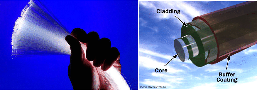
Optical fiber
Copy Right (c) HQLe
Loading package
Overview and study guide
4. The fiber cylindrical geometry
4.1 Introduction
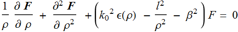
Step 1: Use cylindrical coordinate
4.2 Boundary condition for fiber geometry
Step 2: Set up boundary condition
4.3 Reduction to simpler forms
4.4 The use of S matrix
5. Step-index fiber
5.1 Introduction
5.2 Discussion
To solve for the optical modes, we need to do two
things:
1- Solve the
wave equation (Helmholtz) for each region
2- Apply the
boundary conditions at various interfaces
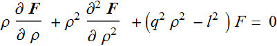
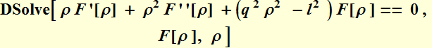
To solve for the waveguide mode, we need solutions of the eq.:
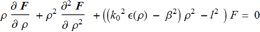
For the step-index fiber, ε(ρ) is constant of ρ for each layer of
the fiber.
Let ε(ρ) be constant, and define ![]()
 (5.1)
(5.1)
![]()
5.2.1 Bessel function solution
5.2.2 S matrix
5.3 Characteristic equation (algebra)
5.3.1 Equation set up
5.3.2 Algebraic reduction
5.3.3 Characteristic equation
The characteristic equation here is thus:

5.3.4 Numerical characteristic Eq. calculation
Source code: mode effective index demo
Demo mode effective index
5.3.5 Concept of degeneracy
5.4 Determine the mode profile
5.5 LP approximation
6 Illustration for step-index fiber
6.1 Review: The number of modes and mode search
Demo mode effective index calc (with λ)
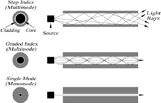
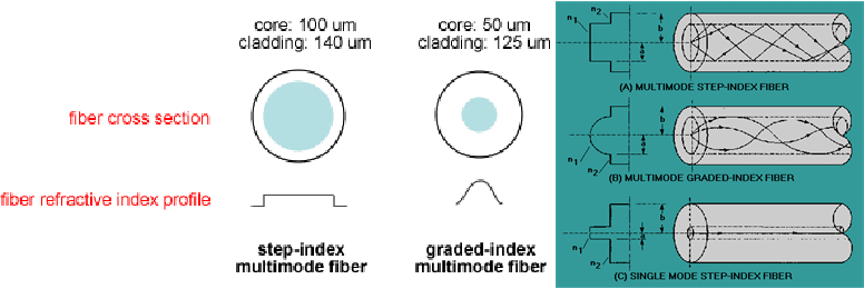
6.2 Key concepts: single-mode vs. multimode, cut-off wavelength
6.2.1 Single mode vs. multi-mode - change of diameter discussion
6.2.2 Single mode vs. multi-mode - change of index discussion
6.2.3 Cut-off wavelength discussion
6.3 Calculation package
6.4 Field profile illustration
Source code - Demo step index fiber - field illustration
Demo step index fiber - field illustration
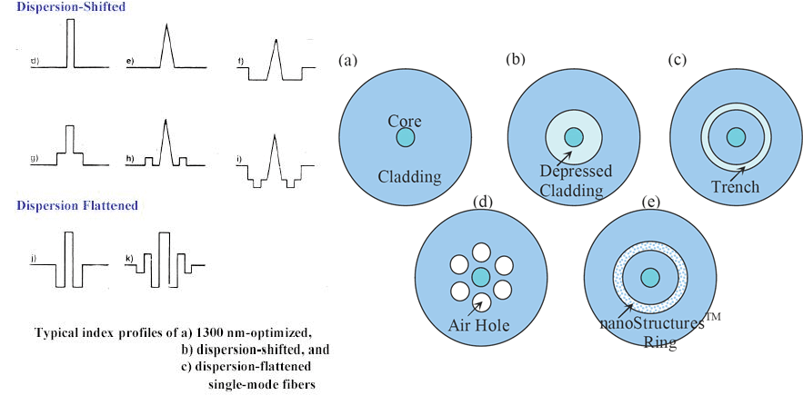
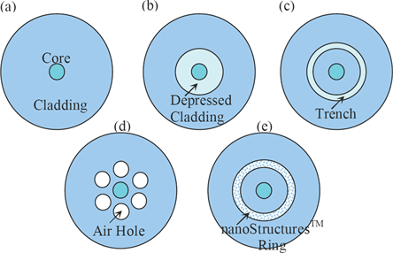
7. Other types of fibers
7.1 Discussion
There are many ways to make fibers and waveguides, and in practice, there are other types of fibers.
7.2 Summary key points and issues in fiber design
1- Optical fibers are waveguides with cylindrical
geometry although this is NOT necessary and some
special-application fibers have elliptical cross section
(polarization-preservation fibers). (Note that planar waveguide
has rectangular cross section.)
2- A fiber can be designed to be single-mode or multimode,
depending on the index profile and the size of the core. The
larger the index difference and the larger the diameter, the more
modes a fiber may have. Multi-mode fibers are designed with many
times larger diameter than single-mode fibers. Each mode has an
effective refractive index.
3- A fiber is designed for a certain wavelength range. For a given
fiber, it can be multi-mode with shorter wavelengths, single-mode
for certain wavelength range and may not have any mode for
wavelength longer than certain value called cut-off wavelength ![]()
4- The modes depend on the detailed index profile of the fiber,
which is a design parameter so that specific properties can be
optimized.
- Mode size is a measure (defined, not
fundamental) to describe roughly how large the field spatial
profile is (it is roughly around the diameter of the core in many
cases, but NOT all cases). [Note: Mode spatial profile is not
important for the detection, which depends on only the total
power.]
- A very important property is dispersion.
5- Dispersion includes: material dispersion, (modal) chromatic
dispersion, intermodal dispersion (if multi-mode), and
polarization dispersion. This topic is important and will be
treated in details in subsequent chapters. It determines how much
information that can be sent through a fiber (its bandwidth x
reach)
6- Designs are done with numerical methods (e. g. software
package) using basic principles of how the various properties vary
vs. design parameters.
7.3 Graded index fiber
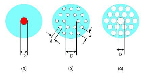
7.4 Holey fibers or PCF (photonic crystal fiber) and PBG (photonic bandgap) fiber
7.4.1 Concept introduction
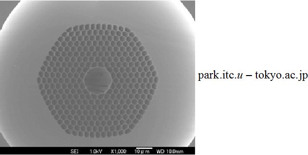
The general concept of dielectric waveguide is to have a high-index core relative to low index cladding. An innovative way of doing this is to �drill� or remove materials of a uniform medium unevenly to leave a core that is �denser� (hence higher index) than the surrounding (hence lower index). Holey fiber is invented as shown below
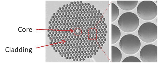
Although the calculation is complicated, it can be shown that waveguiding occurs. The hexagon shape is the tightest 2-D periodic lattice packing of the �holes�, but other arrangement, like a square lattice would work also, although it is less well matched to the cylindrical geometry. The essence of the waveguiding mechanism is still of the fact that the center region index is slightly higher than the surrounding, similarly to the dielectric fibers discussed above.
It turns out that there was a very similar concept
called photonic bandgap materials or photonic crystals. This
concept is related to the problem of electrons in crystals.
In a periodic structure like a crystal, quantum mechanics shows
that the electron energy and wavefunction have certain unique
properties. In particular, the energy forms structure knows as
energy bands with �gaps� between them. In other words, there are
�forbidden� energy range in which the electron does not have any
state. It means that at certain frequency (related to energy with
the Planck�s constant: E=hω), the
electron doesn�t have any propagating wave solution.
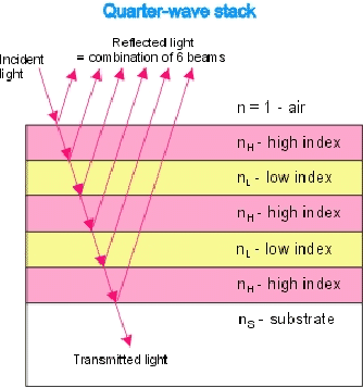
There is a similar situation with optics in periodic media. For one-dimensional periodic thin films, there is a structure known as Bragg reflector. It is a periodic structure in which certain range of frequencies will be strongly reflected (no propagating solution exists) while others can transmit freely. These frequency ranges are similar to energy �band gap�, hence the expression �photonic bandgap�.
The concept is applicable to 2-D or 3-D periodic
optical materials, and hence the term photonic crystals, which can
be applied to make waveguide fibers. However, here, there is a
subtle difference with the waveguiding mechanism in the holey
fibers discussed above. The light is confined by a surrounding 2D
lattice that is designed such that in the transverse dimension,
its frequency is on the �band gap� and hence cannot escape
(transmitted) through the wall.
Another way to think of it is like a mirror waveguide.
Nevertheless, all of these are also described as �microstructured
fibers� a generic terms for various caterogies.
www.ipht-jena.de
7.4.2 Various examples of microstructured fibers
 From
spie.org
From
spie.org
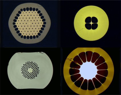
www.ipht-jena.de
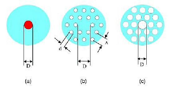
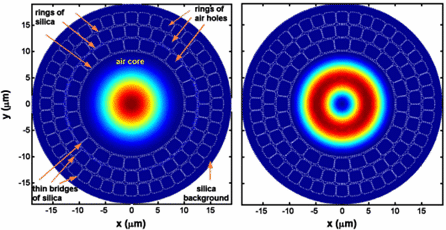
Holey fibers are example of microstructure fibers.
Above is a comparison of different fibers
For the PBG fibers, there is no need for index guiding and the
core can be hollow as illustrated below.
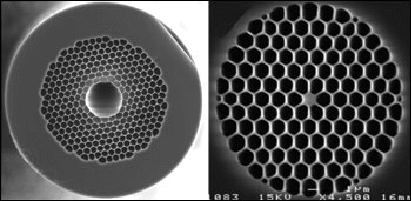
www.math.utwente.nl/aamp/ex_mathopt.html
7.4.3 Summary of advanced types of fiber
Summary:
1- Holey fibers and PBG fibers or PCF offer other approaches of
making waveguides that can provide additional flexibilities in
designing fiber properties
2- Various aspects of the microstructures: hole sizes, patterns,
lattice configuration can be use as design parameters to obtain a
diverse range of properties
3- Some of the properties:
- A wide wavelength band
- A wide range of mode size (from very
small to very large)
- Dispersion properties
- Up to large NA, even for multi-mode
fibers.
- Asymmetry can be used to make
polarization maintaining fiber or to design specific polarization
property
- A number of nonlinear optics
applications
In short, they offer complementary approaches to obtain waveguide
fibers beside the dielectric waveguide fibers.
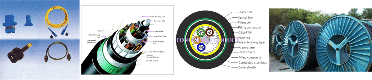
8. Optical fiber and cables: manufacturing
Please see the below
http://www.youtube.com/watch?v=H1Yj-hg2UiU
http://www.youtube.com/watch?v=liKOYbgIC_c
http://www.youtube.com/watch?v=7tsF3mSpqX8
http://www.youtube.com/watch?v=Ncf4jRUQclI
http://www.youtube.com/watch?v=0RYiBqHgOl0
Remember cymatics:
http://www.youtube.com/watch?v=GtiSCBXbHAg
http://www.youtube.com/watch?v=CGiiSlMFFlI