Homework 5
ECE 4339
Han Q. Le (copyrighted) U. of Houston
1. Revisit the circuit problem

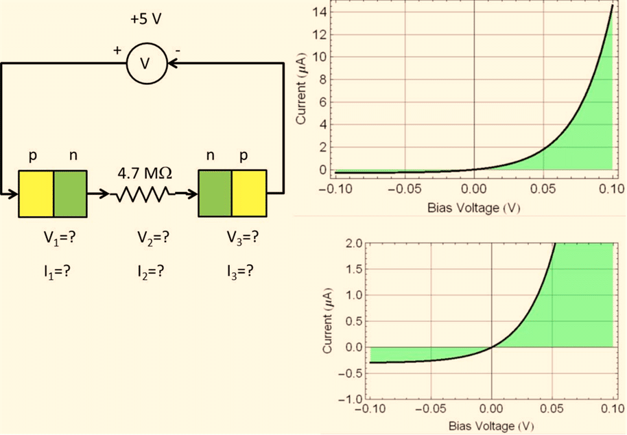
Consider the circuit above. The 2 p-n diodes are identical with the I-V characteristic shown in the graphs. (The lower one is same one as the top graph but with higher resolution on the vertical scale). There are 6 quantities we want to know: the 3 voltages and the 3 currents as shown (with question marks).
Let’s consider the follow arguments and possibilities; Provide a discussion of each: whether you agree or disagree and why.
1.1 The electronic circuit is illogical
Argument 1: The electronic circuit is illogical (or not legal) and doesn’t exist. (Because why would anyone put a back-to-back reversed diode pair with a resistance in between?) Hence, it has no solution because it is irrevelant, illogical, not functional, and certainly not a legal circuit in any electronic circuit textbook. In fact, such a circuit would never “work” in a lab .
Discuss what you think. (Or, how would you answer/explain to someone who says that).
1.2 The problem is unsolvable
Argument 2: The problem has 6 unknowns, but we have only 2 equations: ![]() (volts) and
(volts) and ![]() , hence, it is fundamentally unsolvable.
, hence, it is fundamentally unsolvable.
Discuss what you think.
1.3 Argument 2 is wrong
Argument 3: Argument 2 above is FALSE because it has ONLY 4 unknowns, not 6, since all the currents are the same. Nevertheless, it is still unsolvable because we still have 4 unknowns and only 1 equation.
Discuss.
1.4 The circuit has a solution but...
Argument 4: Both Argument 2 and 3 above are FALSE because the principle that at least n independent equations are needed for n unknown is applicable only for mathematics and not necessarily for electronics. Since this is an electronic problem and not a math problem, it may have a solution, which cannot be solved with mathematics (not enough equations) but can be obtained by building the circuit and perform a measurement.
In fact, Argument 1 is FALSE, because such a circuit can be built in a lab and it won’t blow up (and kill the experimenter).
Discuss.
1.5 The electronic circuit can be solved by part
Argument 5: The circuit can be solved component-by-component iteratively as followed:
Step1: The reverse-bias diode (the one on the right) can only give a maximum current of 3 μA.
Step2:At 3 μA, the forward-bias diode (the one of the left) has a voltage of 0.02 V. Hence, we solve for one unknown: ![]() V.
V.
Step3:At 3 μA, the voltage across the resistance is: ![]() . Hence, we solve for another unknown:
. Hence, we solve for another unknown: ![]() V.
V.
Step4:Since we know ![]() and
and ![]() , we can derive
, we can derive ![]() :
:
![]()
Thus, we have solved the circuit completely:
![]() ;
; ![]() V;
V; ![]() V; and
V; and ![]()
Note that all the equations in Argument 1 or 2 are satisfied with the above answers, hence we obtain the solution for 6 unknowns (or 4 unknowns) without requiring either 6 or 4 independent equations. This proves the validity of Argument 4 that the math principle of “n independent equations for n unknown” is not applicable to electronics.
1.6 The problem has enough equations but...
Argument 6: There are enough equations: if we view the problem as having 6 unknowns, we have the following 6 independent equations:
Eq. 1 ![]()
Eq. 2 ![]()
Eq. 3 ![]()
Eq. 4 ![]()
where F(j) is the given I-V characteristic function of the diode.
Eq. 5 ![]()
Eq. 6 ![]()
where F(j) is the same given I-V characteristic function of the diode as mentioned in Eq. 4.
However, it is fundamentally unsolvable because F(j) is not a linear function; and non-linear equations cannot be solved as a matter of fundamental principle. Besides, it is a moot point because the solution in 1.5 above is already a good enough approximation.
1.7 What is the solution?
If you disagree with all of the above (especially the answers in 1.5), what is your solution? (best approximation with graphical analysis).
2. Narrative explanation of BJT with hydrodynamic analogy

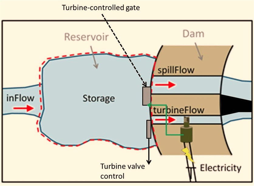
Suppose you want to explain how a BJT works to someone who doesn’t know anything about semiconductor (and electrons, holes, etc.). You wish to use a hydrodynamic analogy as shown above. Write a narrative explanation. Make sure you identify the equivalent role of each functional component.
(For example, what is the “storage” functional equivalence in a BJT? What channel is equivalent with Base, which one is equivalent with Collector. What is the equivalence to the control of the turbine valve, i. e. when you vary the turbine valve, what is the equivalent thing you vary in a BJT? What should the relationship beween the turbine flow and the spill flow be in order for it to work like a high-gain BJT? etc... you can write as detailed as you understand how the BJT works - remember, you are explaining to someone who may know how to use a BJT as a current amplifier, but doesn’t know semiconductor physics and devices).