

|
|
ECE 2100 Lab. II -
Kirchhoff Circuit Laws -
Advanced level (150
pts.)
|
Important
note:
Lab.
II is to explore Kirchhoff Voltage law
and Kirchhoff Current law. There are two
versions of the lab:
- Basic version: linear circuit with resistors. The basic version in MS format can be downloaded from the course web page. Apps for help are on this page.
- Advanced version: non-linear circuit with resistors and LEDs. Since LED is non-linear, the problem can only be solved with numerical approach for either Node-Voltage or Mesh-Current method.
2. TThis page is the
advanced version. It is designed for
those students who wish to explore and
learn about LEDs. The score for the
advanced lab work is higher, 150 pts
instead of 100 pts to reflect the higher
complexity of the circuits.
Prior to the start of Lab. II, you must make a commitment to either the basic or advanced version by submitting the pre-lab prior to starting. Once you commit to a version, you must follow through with lab work. In other words, your pre-lab and your lab work must match.
Introduction:
| Circuit 1 |
Circuit 2A |
Circuit 2B |
Since the circuit cannot be solved with linear (matrix equations) method, we must use numerical approach.
First, let's take a look at LED circuit behavior:
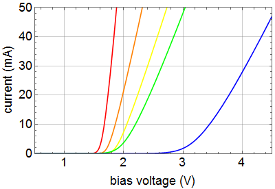
| Current vs.
Forward Bias Voltage for red, orange, yellow,
green, and blue
LED |
Forward Bias Voltage vs. Current |
 |
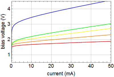 |
A typical LED is different from a typical diode with regard to two properties:
1- the contact potential is substantially higher and is a function of the bandgap of the material, which determines its color; and
2- its conduction above the contact potential is more resistive than diode.
Hence,
the ideal diode model is neither
relevant
nor
useful. As we can see above, different
color LEDs have different I-V
characteristics that must be
realistically taken into calculation.
Furthermore, the above curves are only
nominal, as there is great variation
of electrical characteristics among
nominally the same color LED's, and
the variation can be significant even
among those from the same batch by the
same manufacturer. The reason is that
the series resistance and the thermal
behavior are quite sensitive to the
fabrication process and packaging.
Hence, the above phenomenological
model is useful as a rough guideline,
but a circuit can only be calculated
accurately only with actual specific
device data.
Numerical
methods for KVL equations
For the three
above circuits, The three sets of
KVL equations are: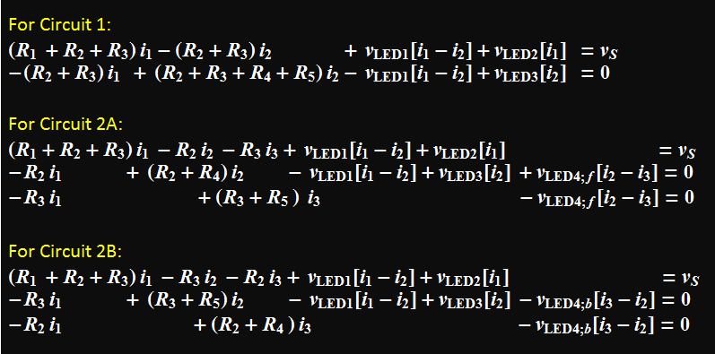 |
If you are curious how
the above equations can be coded to do
numerical calculation, here is the
code for Circuit 2A (you can do
minor modification yourself for other
circuits). Here is the Mathematica
notebook that you can download and
run. (Just select, shift+enter)
The
first circuit is quite simple with just
two equations as shown at the top set.
The other two circuits, 2A and 2B
involve a bi-directional LED, which has
different characteristics for the two
directions. One is a green LED, the
other is amber. Circuits 2A and 2B
involve swapping the positions of
resistor R2 and R3, and the positions of
R4 and R5. This results in opposite
current direction through LED4, which is
the bi-directional and the color change
serves as a current indicator.
The above sets of equations are numerically solved using multivariate secant method in the app explained below.
The circuit can
also be solved with KCL equations, i.
e. the Node Voltage Method. However, numerically,
this method is less advantageous compared to
MCM as we can see below.
The
unknown
variables to be
solved
for are
high-lighted
in green.

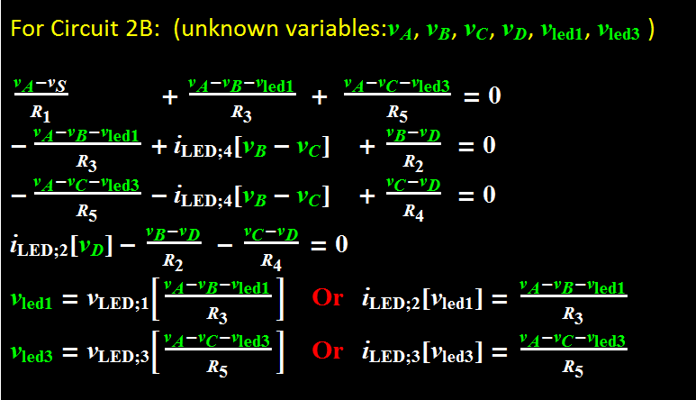
Clearly,
there are more equations to
solve, and a practical algorithm is as
follow:
1-
Assume initial value of
vled1, vled3,
vD.
2-
Solve for vA, vB, vC
3-
Substitute
vA,
vB, vC and
solve for vled1, vled3,
vD.
Iterate
until satisfactory
results are
obtained.
It is more
labor
intensive than
the MCM that
have fewer
variables.
Main app for the Lab
| The app has 2
panels: The left panel provides
choice of the circuit, animation
control and size of current arrow. The right panel provides controls for circuit parameters and optional display of calculation results. |
|
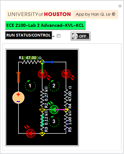 For .cdf file: For slower computer, a slightly less graphical app is here |
 |
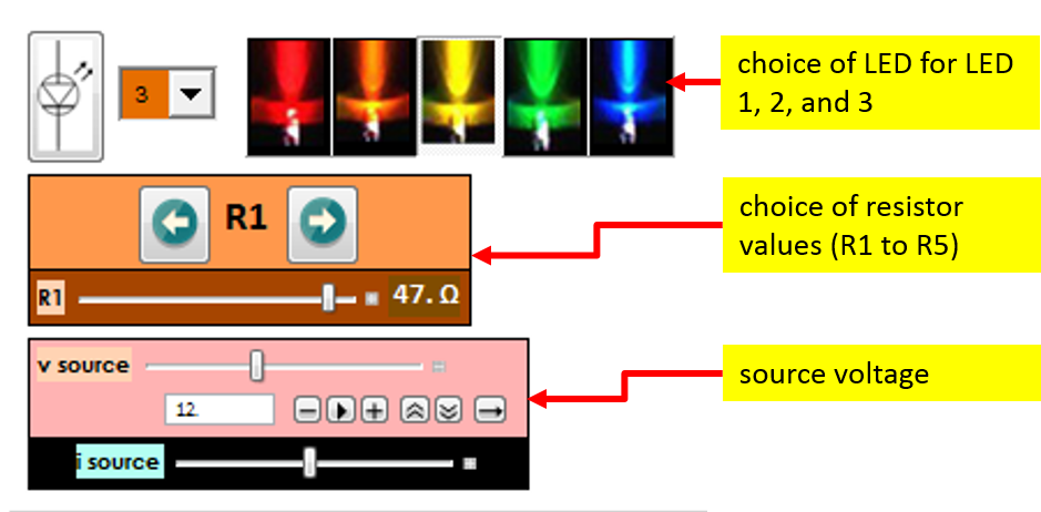
The circuit is designed for the default resistor values to illustrate the effect. The values should not deviate more than +-25%. The LEDs can be any of the five most common colors. They do not have to be the same for all three, each can have its own color. Only LED 4 is special. However, one can, in destitute, substitute the bi-directional LED with two parallel and directional-opposite LEDs.
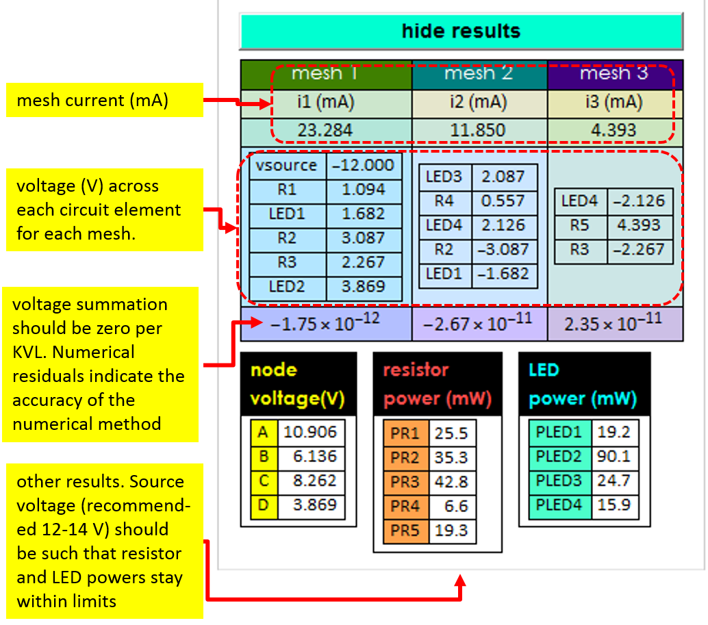
It is important to keep in mind that this calculation is based on the phenomenological model of LED characteristics shown above. Actual LEDs can be different, hence exact agreement between calculation and experimental results should not be expected. However, that is not important. The objective of this lab is to demonstrate KVL and KCL. Hence, you are expected to do measurements of voltages of the various meshes and add them up to verify that they are zero within experimental uncertainty. You will also measure the node currents at two nodes: B and C to verify KCL.
Lab work outline -
please see write-up
for details
For pre-lab, also follow
the red letter
in the write-up.
Step
1 - Circuit 1
1.1
You will be given 2 x 47 Ohm or 50 Ohm
resistors. Although you should
have the resistors or LEDs listed, you
can choose similar elements based on
what you have. For example, if you have
yellow LEDs instead of red, you can
certainly use them, or mix whatever
colors you have. For resistors, you can
use a substitute that is within ~±25% of
a suggested value if you don’t have the
right one.
Once you start, stay with the same
elements you have, in other words, don’t
change resistors or LEDs from one
circuit to the next. All three circuits
are really of the same basic
configuration
1.2
1.3
1.4
Perform measurements and record the
results based on Table 2 above. In
your Lab notebook, you must tabulate and
clearly show a column for calculated
values of voltages and currents (based
on the APP with actual values of your
resistors) and a column of corresponding
measured values. Next to these two
columns is the relative deviation. Your
deviation can be easily 5, 10% or more,
because LEDs have great variation, even
by the same manufacturer within the same
batch. But that is not important. Your
actual measurements are what important
here.
1.5
Test Kirchhoff voltage law. Add the
measured voltages of all the circuit
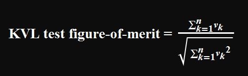
elements in each loop. KVL states that
it should be zero. Take your results,
divide it by the root-sum-square of
them, that is your figure-of-merit,
report and write your discussion (e. g.
KVL is verified up to 1 part in 10^4,
limited by instrument precision, etc.)
Step 2
- Circuit 2A
2.1
2.2
2.3
Create Circuit 2A by inserting the
given bi-directional LED between B
and C such that you get green
light instead of amber. Perform
the same type of measurements and
test as you did in 1.4 and 1.5
above. Tabulate your results
neatly.
2.4
Report what you observe about the
relative brightness between LED1
and LED3 before and after
inserting the special LED (LED4).
2.5
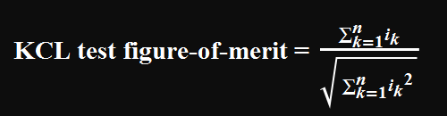
Test KCL law: Perform current
measurements at node B and record
in your lab notebook like Table 4
below (make sure you get correct
sign. Negative for the first 2 and
positive for the last).
3.2
3.3
3.4
Build Circuit 2B by doing what you
observe in 3.1. Report in your lab
notebook color change of LED4 and
discuss what causes it. Do you think
what applications bi-directional LED can
be used for?
3.5
Perform the same type of measurements
and test as you did in 1.4, 1.5, and 2.3
above. Tabulate your results neatly in
your lab note book. Comment on your KVL
test.
3.6
Test KCL law: Perform current
measurements at node C, do what you did
like 2.5 above. Again, discuss how good
your KCL test is at this node.
Write what you think of
your study of KVL and KCL of this lab.
Do you think LED is a good indicator of
current flow? What do you learn
(personally) in this lab?