| |
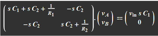
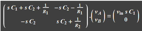
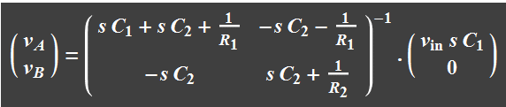
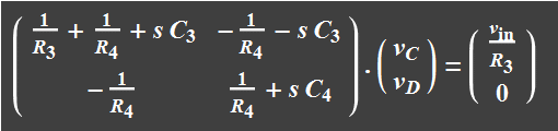
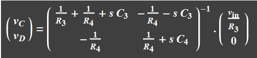
which can be
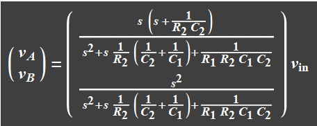
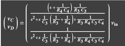
solved:
Active
circuit - high
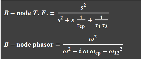
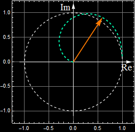
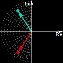
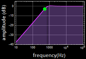
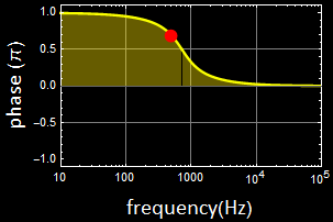
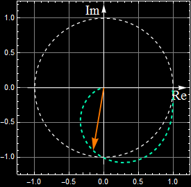
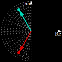
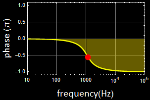
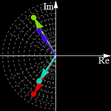
pass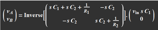 => => 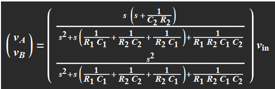 This gives the result: 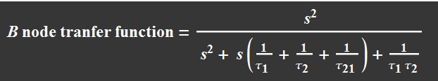 and and 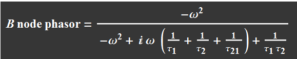 Phasor plot on the complex plane  Phasor and Bode plots 
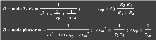
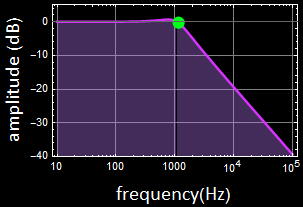
Active circuit - low pass
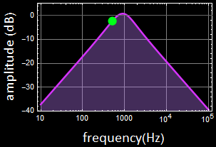
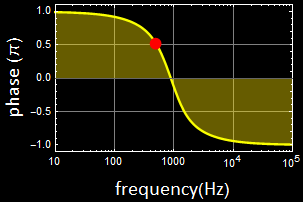
Active circuit - band pass The transfer function for the above bandpass filter is simply the product of each part of the circuit. It is customary to assume that the output impedance (Thevenin) of the first op amp is small and negligible to the input impedance of the second circuit. 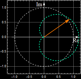
  |