

|
|
ECE 2100 Lab. VI
- AC Signals, Linear
Circuits, and Second-Order
Filters
Please
download these
items:
1. Lab 6 workbook and report 2. ECE 2100_APP_Lab6_wiring_help ECE_2100_APP_Lab6_2nd_order_RC_filters Other useful app: |
Page 3
Please go to update pages for the latest modification, class-wise issues, and others if links for those pages exist.
update page a update page b update page c
| Lab work
modification: |
Part B: Low-pass filter
Step 0
Background on the low-pass filter
Step 1
Build the low-pass filter circuit. Please download the wiring help app.
Please refer to the picture of the circuit above for additional help
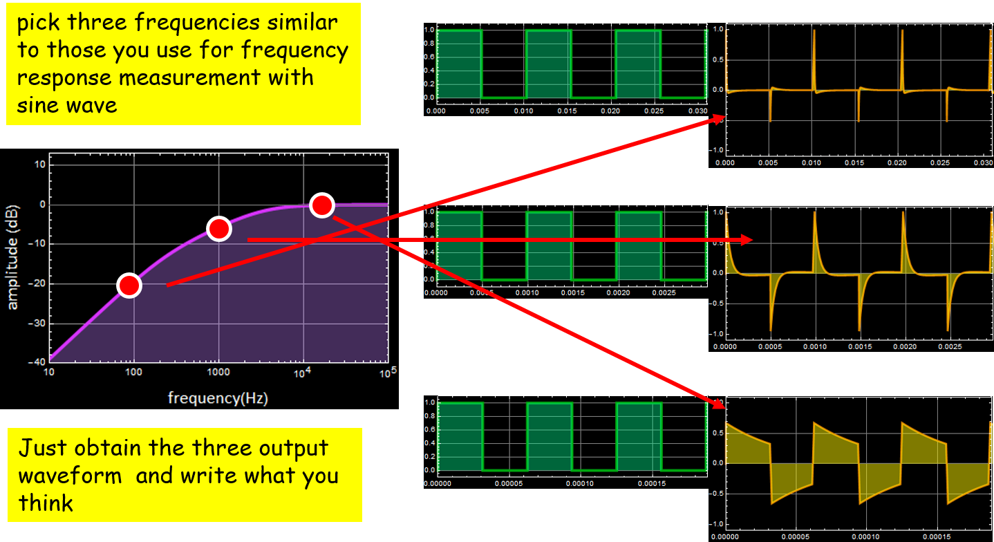
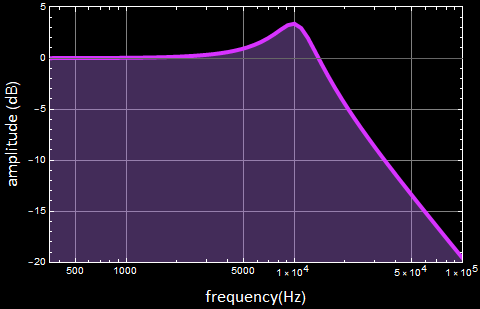
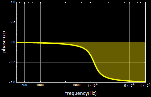
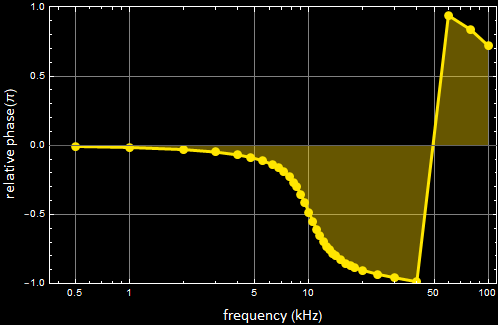
Step 2
Frequency response: Please see the circuit simulation app for theoretical calculation, to be compared with experimental measurements. Below is an example: the results of the circuit in the photo.
Theory: From circuit simulation app:
Bode magnitude Bode phase
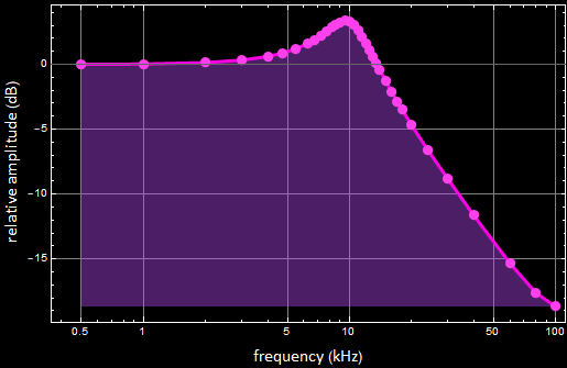
Experiment: For the actual circuit in the photograph:
Bode magnitude Bode phase
Theory:
From circuit simulation app:
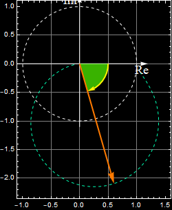
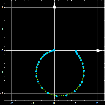
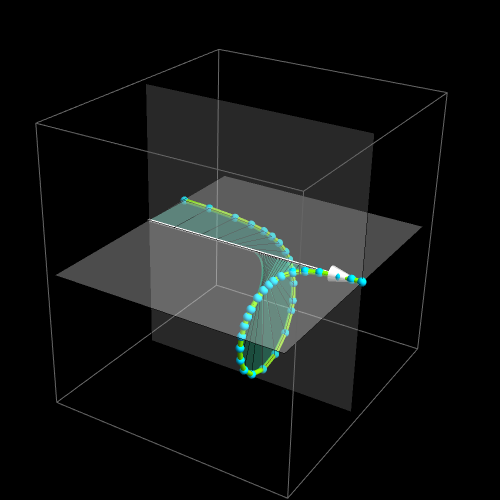
Experiment: For the actual circuit in the photograph:
Nyquist 2D Nyquist 3D (white horizontal arrow is Log frequency)
Step 3
Step response
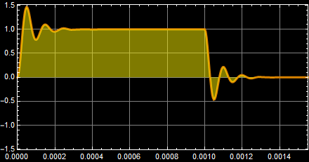
Theory: from circuit simulation app:
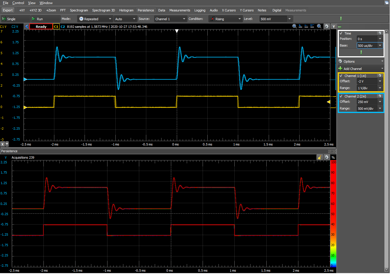
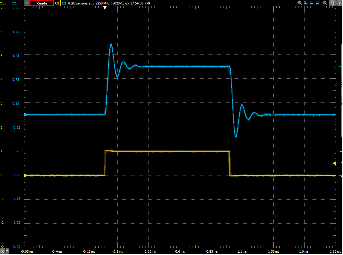
Experiment: Step response - from the actual circuit:
Step 4
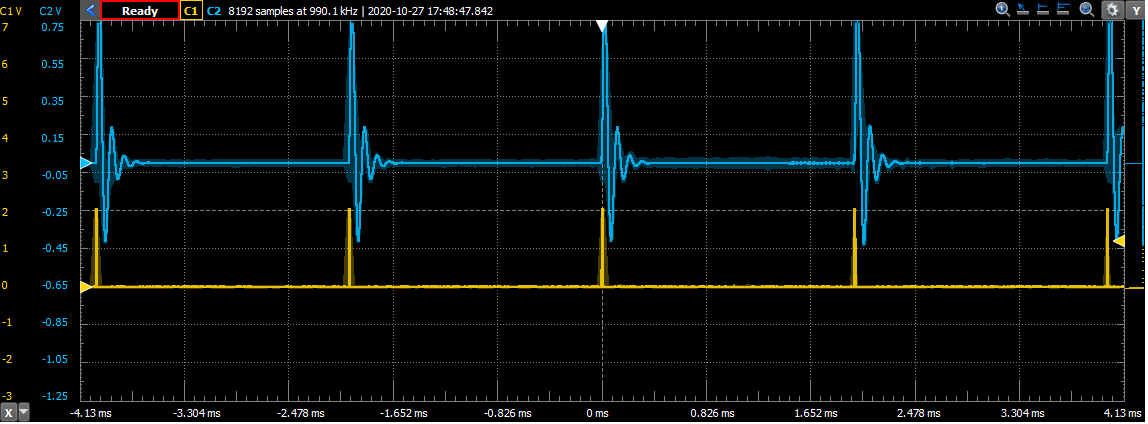
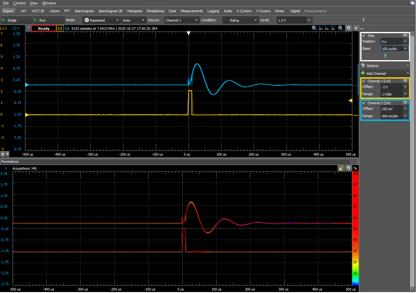
Experiment: Impulse response
End of Part B
Continue to page 4