

About
running apps:
- If you
have Mathematica(R),
download the .nb
APP files.
- If you
don't have Mathematica(R),
you will need to
download the
free Wolfram
CDF player
. Then download
.cdf
 APP
files and run.
APP
files and run.
|
|
(continued
from page
1)
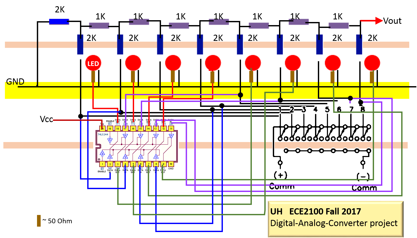
Additional thing to learn: We know that the resistors have quite a bit of variation, especially if you have only silver-band (10% variation) or gold-band (5% variation) resistors. If so, how well does your DAC work? 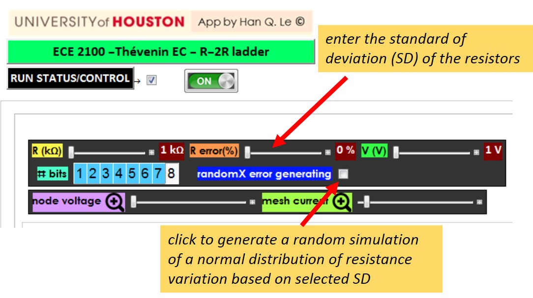
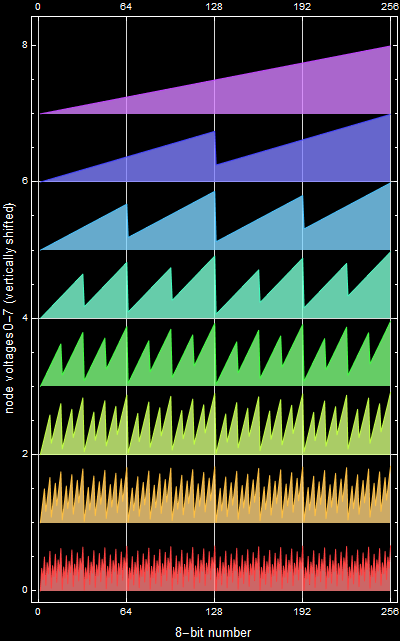
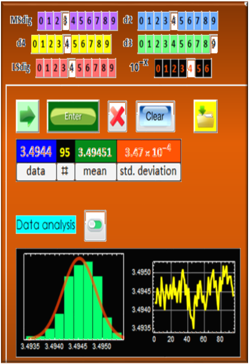
Items in your report: You will input a text (see the example below) that includes your name, student ID, and up to 160-character summary if you wish, of what you accomplish in this project. You will obtain the output signal and submit the chart as shown. (Very easy if you use the Apps developed for this course. For example, you can use this App on the Course App page to enter the output voltage as you flip the bits on-off). It would be even easier when you can program an Arduino or Raspberry Pi to output 7-bit ASCII binary code as input into your circuit and use Labview GPIB control of your DMM to read into your computer. You might not be able to do this yet in this course, but you will be by the time you are in Senior Capstone Design. This course is a beginning.  If you want to hear what your signal sounds like, you can make an array of repeated signals, select a sampling rate (e. g. 8 kHz, 11.025 kHz, 22.050 kHz etc.) and ListPlay it with Mathematica. (you can remove space character, which is "32" in decimal and %20 in hexadecimal that gives a high-frequency shrill component). For example, this is the sound of the above signal without space characters: Did you listen to the sound? If you did, you just witnessed a digital-analog-conversion: your digital device (computer, tablet, or phone) has a built-in DAC that converts the digital signal we have into an electrical signal that drives the speakers so that we can hear. Appendix See below how to analyze your data. If you want an example of data file: download this: DAC_data_example. Put the file in any folder that is easy to access. For WIN OS, it is suggested that you put in My Documents. Any folder is OK as long as you know where it is. You can use the APP to open this example data file to see how it works. 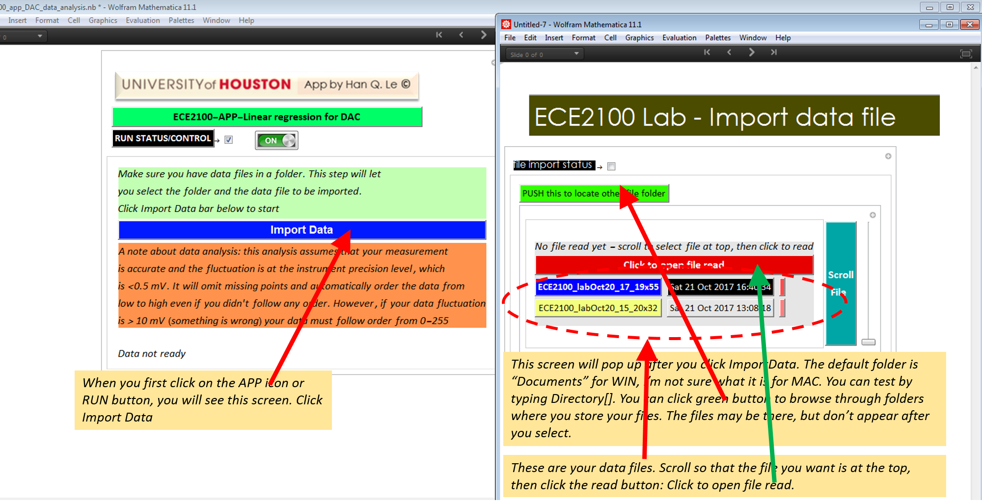 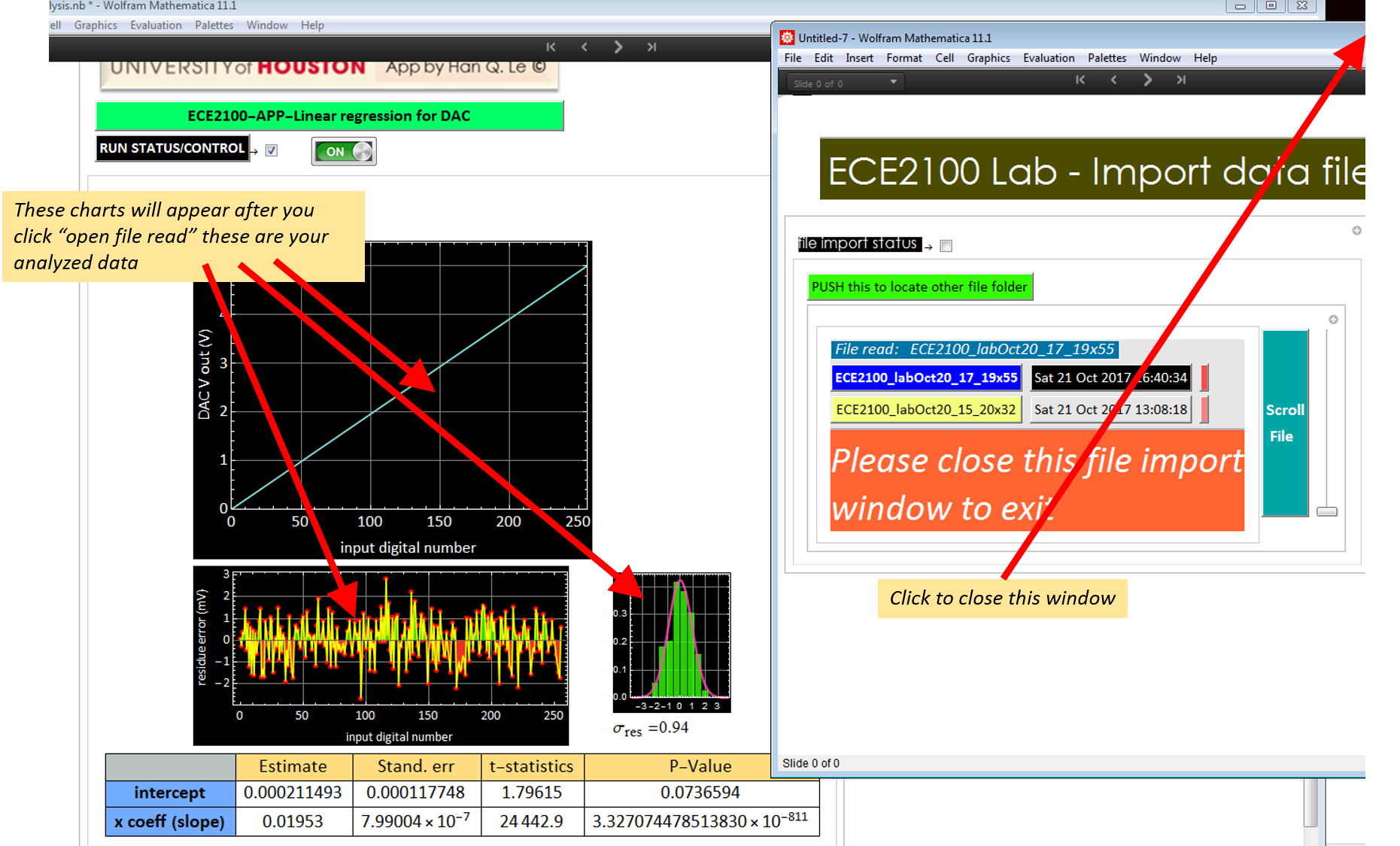 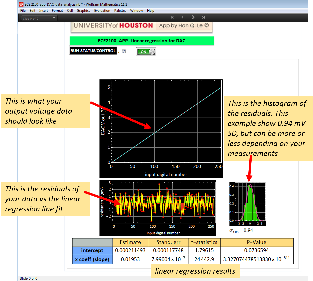
|
|||||||||