About
running apps:
- If you
have Mathematica(R),
download the .nb
APP files.
- If you
don't have Mathematica(R),
you will need to
download the
free Wolfram
CDF player
. Then download
.cdf
 APP
files and run.
APP
files and run.
|
|
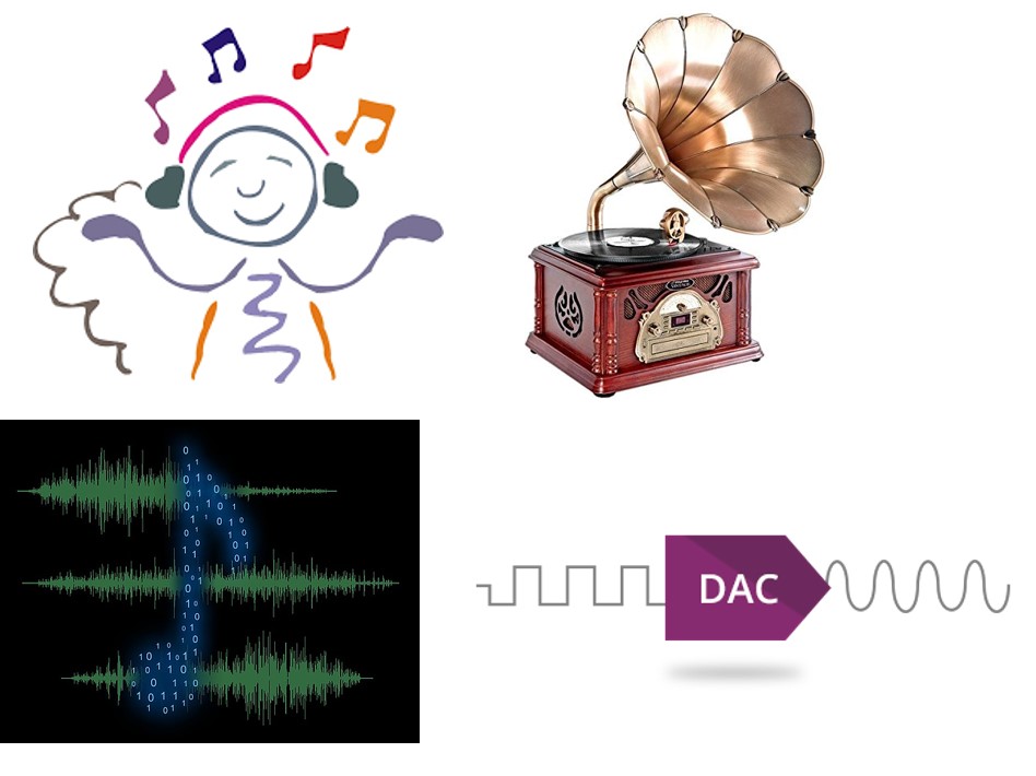
Introduction:
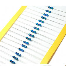
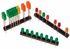
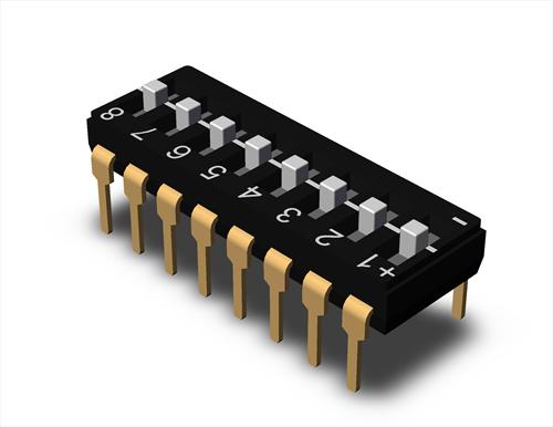
Discussion and suggestion: The first answer is: "No, you can't buy a ready made chip to do the job." You will have to design and build one, and of course, you are expected to go through tried-and-true designs, of which one of the best known is R-2R ladder circuit. Below is an illustration how it works. Here is an APP that helps you analyze the data: (if you have problem, contact the instructor for help - the APP is designed with the assumption that the measurement fluctuation is roughly the same as the DMM precision. If the error is much larger, it may indicate something wrong. Note that this analysis should help to illustrate the concept of error due to the errors of the resistors which is different from the concept of error due to the precision of the instrument). Components: you will need:
continued on page 2 |
||||||||||||||||||||||||||