About
running apps:
- If you
have Mathematica(R),
download the .nb
APP files.

- If you
don't have Mathematica(R),
you will need to
download the
free Wolfram
CDF player
. Then download
.cdf
 APP
files and run.
APP
files and run.
|
|
1.
Objective:
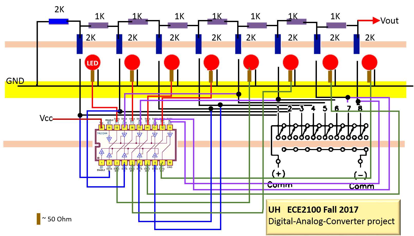
Here are related materials: pre-lab: Wiring diagram: 2. Introduction: Consider the circuit below.

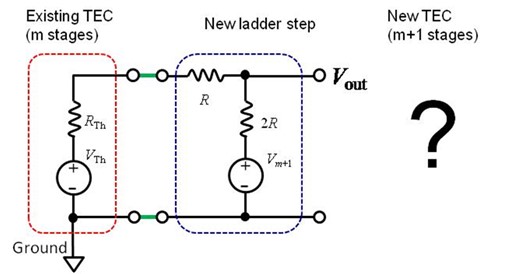
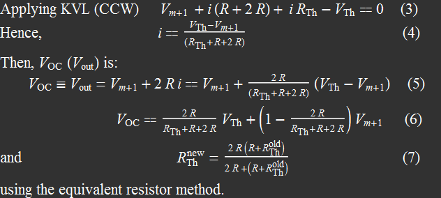
3. Description: How do we analyze this circuit? If we use either node voltage or mesh current method, we will have 8 equations with 8 unknowns (8 node voltages or 8 mesh currents). It is certainly impractical to solve the circuit this way. Imagine what happens if we have 16 bits? However, we can use a method that you learn in ECE 2201, the method of equivalent circuit with Thevenin's or Norton's theorem. You will conduct measurements that verify Thevenin's equivalent circuit theorem to understand how to solve this R-2R resistor network. The circuit is actually a lot simpler than you might think. The reason is that it is just a repetition of a basic step like a ladder: if you know how to make one, you know how to make them all as shown below.  It can be built one step at a time. Look at the start: it begins as just a simple, equal-segment voltage divider: splitting V0, the bit-0 voltage into two with 2 2R resistors. Then, we connect the bit-1, V1 ladder step to its output (the red node and ground). Then, we connect again with an identical structure ladder with bit-2, V2 voltage, and so on. All ladder steps are structurally identical: a voltage source representing the added bit with two resistors (2R and R) in series. The left side is connected to the existing ladder, and the right side is the output. The exact value of the bit voltage of a ladder is irrelevant to solving the problem. It is just a voltage source. Consider we have, say a 4-step ladder. What happens when we add the 5th step to it? If the entire 4-step ladder can be represented with a Thevenin's or Norton's equivalent circuit (the illustration above uses Thevenin's EC), then we can solve the problem quite easily with the added 5th step (shown as m+1, m=4)
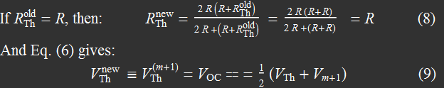 A very simple result indeed: The new ladder with a new step has exactly the same Thevenin resistance as the old one. In fact, you now can infer that if the first ladder has Thevenin resistance = R, then every ladder after that has exactly the same Thevenin resistance. And for the voltage, the new Thevenin voltage is just 1/2 of the sum of the previous Thevenin and the new ladder voltage. Let's substitute: 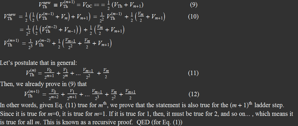 It is equally simple to solve each step with Norton's EQ as shown in the Figure below 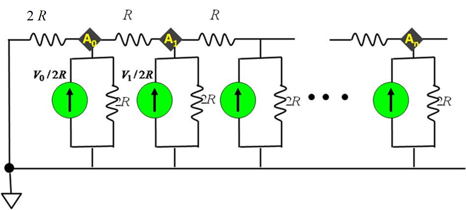 In essence, this lab is designed for you to carry out experimentally the steps we show in the recursive proof: you will show experimentally that the Thevenin resistance is the same for all ladders, and that the Thevenin voltage for each successive ladder you add is 1/2 of the sum of the previous Thevenin voltage and the new ladder voltage. 4. Components and Circuit Layout You will need:
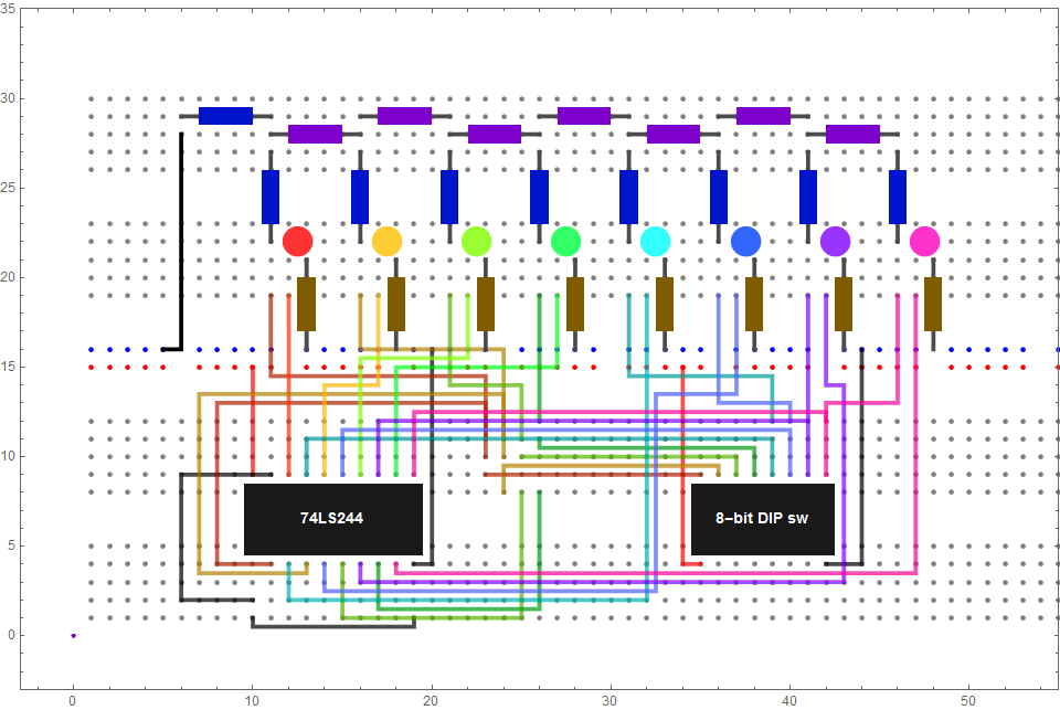
You should use bit-ON voltage 5 V. This is the
ultimate layout. Nobody will
stop you from wiring it
ahead at home. However, you
are supposed to assemble the
R-2R ladder one step at a
time and do measurements in
the lab. So, you can prewire
the everything except for
the resistors. You can put
them in place, but will pull
out to do measurements.
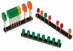
 5. Measurement and Analysis It is actually very simple. The idea is that you put in the resistor network last, after the LED and the switch. You can put in all the LEDs, switching them on/off just for fun. But the LEDs serve a very important purpose as you see below. You will build it one ladder step at a time and take measurements as shown in the table below.
1- Note that you don't start out with step 0 because it is just too simple as a voltage divider. Hence, you start the measurements with 2-step ladder: bit-0 and bit-1. 2- All bits are assumed to be set to 1, i. e. turn all on when measuring V open, and I shorted after adding each ladder step. 3- To measure the equivalent resistor with the Ohm-meter, YOU MUST FLIP ALL THE BITS TO ZERO: in other words, ALL LEDs MUST BE OFF <-- this is what they are for. 4- If you already built the R-2R ladder at home, you can do the measurements in reverse: start with bit-7 and work backward. Pre-lab Your prelab is to fill the table with expected values, which... is trivial. You should know by now what all the entries of the last two columns should be. Use Eq. (9) above to figure out other entries, check with the R-2R ladder APP to ensure you get them correctly. One important aspect is error analysis. All resistors are rated 1%. It is really impractical to measure the actual values of the resistors and check with the actual circuit. Hence, This is what we do: - as a part of your pre-lab, but not turned in at the beginning, you will measure the deviation in % of all 18 resistors you will use. Use this data entry APP to obtain its standard of deviation, e. g. 1.5%. Submit this with your table above as pre-lab report. After finishing the table with measurements, you are done on that part. Next, check for deviation of your Vout and its expected value. The APP allows a simulation of R-error by generating a normal distribution of R-values and calculating the output node voltages. You don't have to do anything other than reporting your results. Then, the instructor will compile the data of the entire class and compare with simulated results for the whole class to use for discussion. 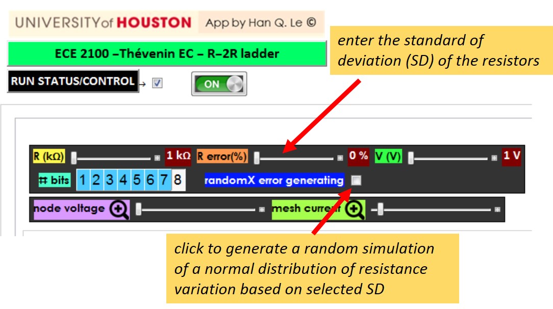 6. Summary and conclusion Write a paragraph about what you learn applying Thevenin EC concept to each successive ladder step construction. Extra: Some nice circuits from other classes: 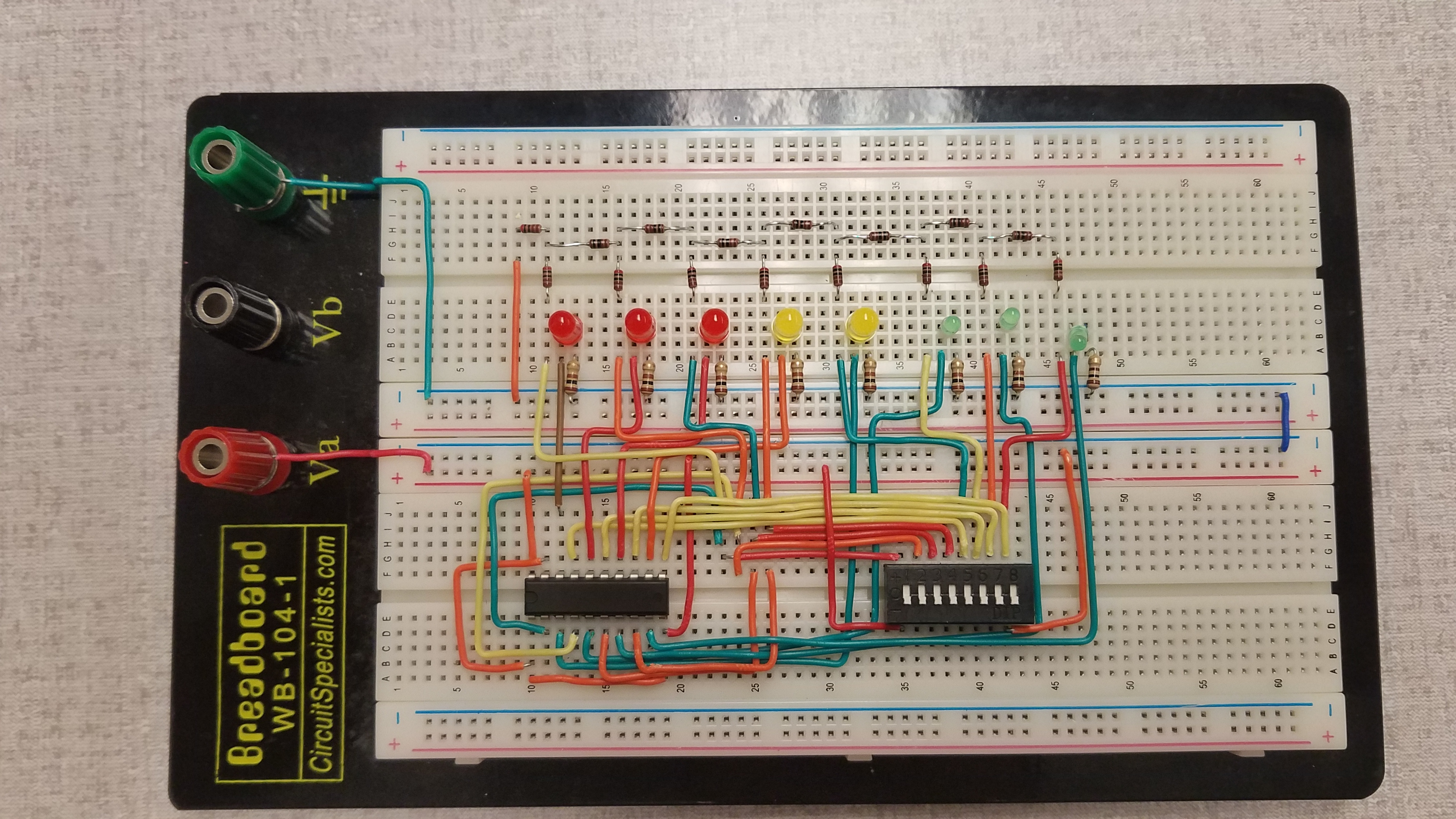 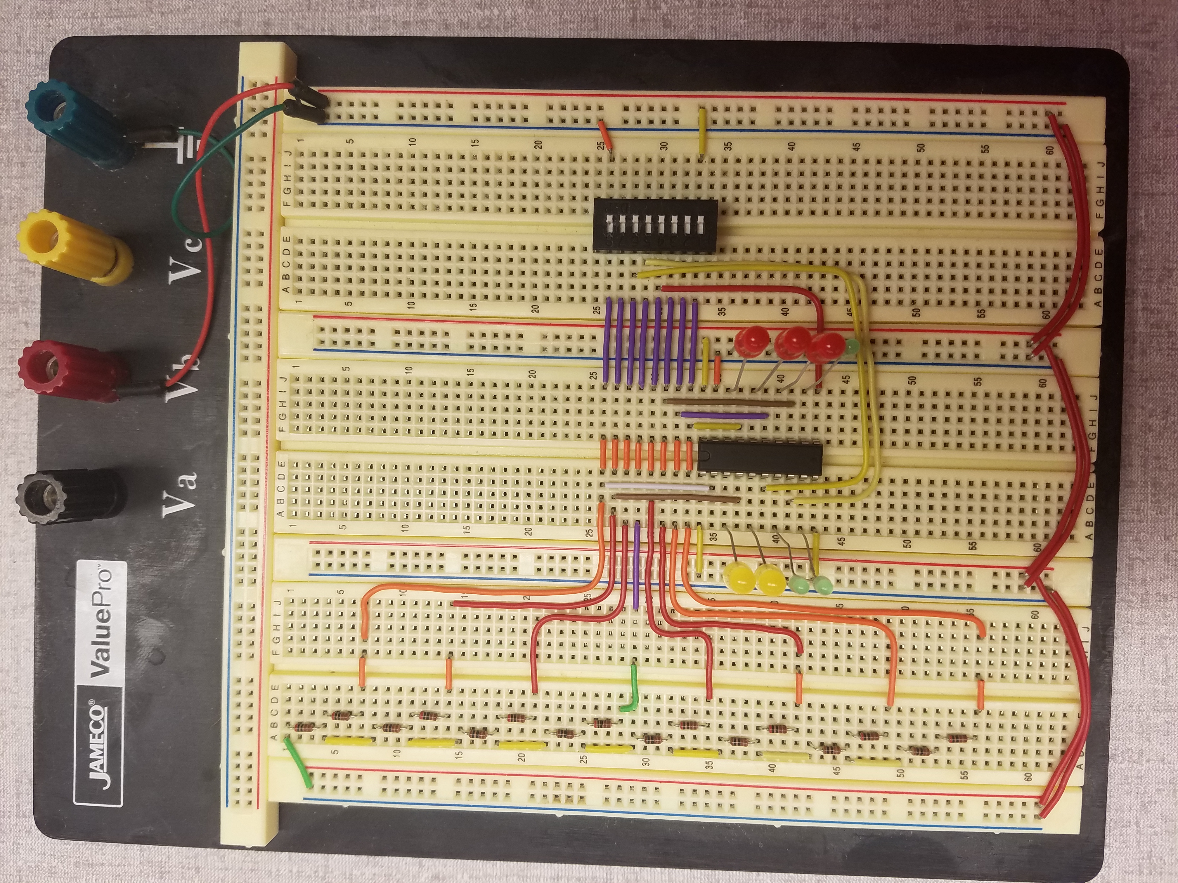 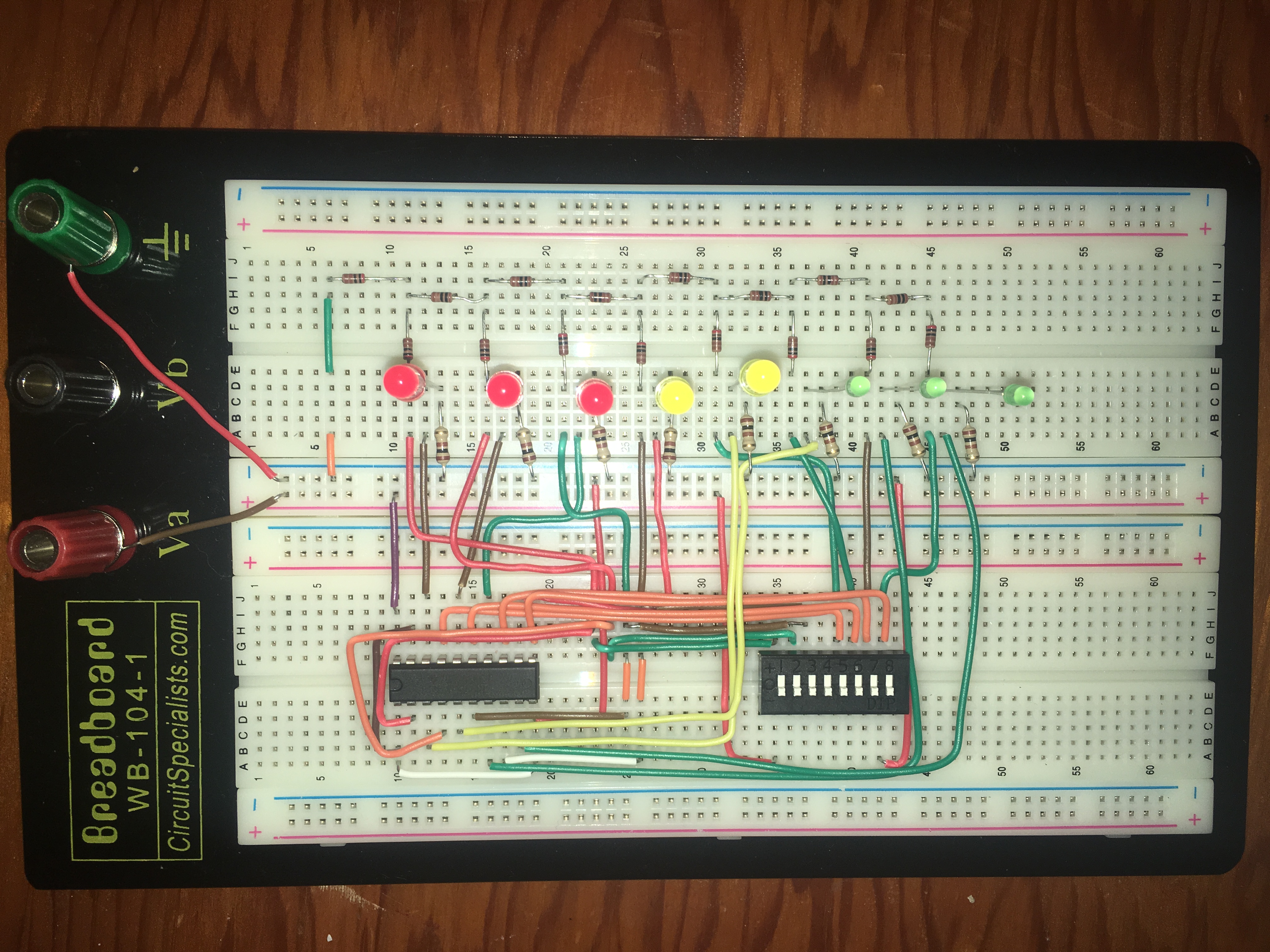 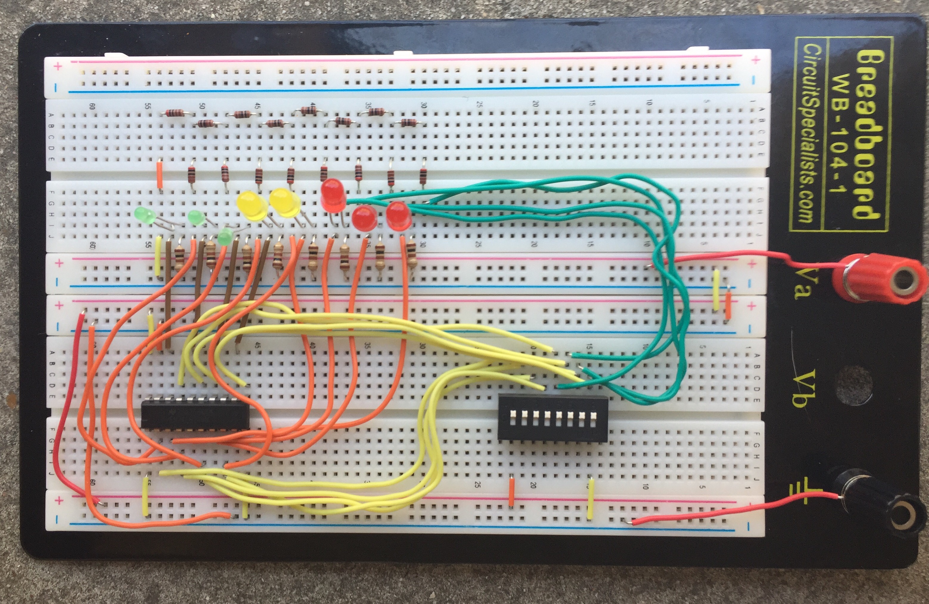 |