|
|
ECE 2100 Lab. II -
Kirchhoff's Circuit Laws,
Wheatstone and Rectifier
Bridges.
Please
download these
items:
1. Lab 2 workbook and report 2. ECE 2100 App Lab_2_guide Part Intro and Part A Special guide: ECE 2100_App_Lab2_KVL_measurement_guide for Part A Step 3 and 4 Special guide: ECE 2100_App_Lab2_AC_DC_rectifier_circuit_guide for Part A Step 5 ECE 2100 App Lab_2_guide Part B and C |
Labwork:
| For this Lab and
like all others, circuit simulation
apps allow understanding as well as
to check lab work. The accuracy of
app calculations should be better
than a few percents, if not <=
one percent most of the time. The
discrepancy between calculation and
measurement is usually due to
circuit elements' manufacturing
variation compared to model
calibration. Hence, if you see a discrepancy more than 10%, it should be a warning, perhaps some circuit elements degrade or not what you think they are (a most common mistake is wrong-value resistance; second most often is degraded solid state devices, e. g. diodes, transistors, or IC chips). If you see 20% or more, that is definitely a red flag, often indicating wrong circuit wiring, accidental shorts, parasitic connections, or perhaps you are not measuring the right thing. Always report relative discrepancy (error) in your Lab reports. Don't worry if a discrepancy is less than 5%. Do some checking if it is above 5%. |
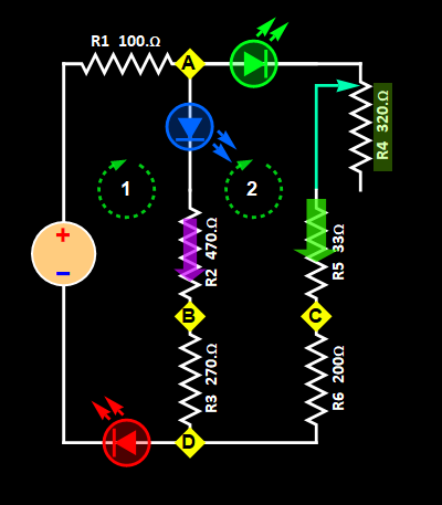
- Part A: LED rectifier circuit
Fig. 5
![]()
- Step A1:
Build the circuit above. You can use
other LED colors as you have/wish, but
the default color scheme as shown is
recommended so that you can identify the
circuit meshes on the breadboard.
If you use a different color scheme,
make sure selecting the correct LED
colors in the App associated with this
circuit.
- Step A2: Chose
a positive source voltage between 7-8 V
(recommended 8 V). You can go a bit
higher or lower depending on your LEDs,
but the key criterion is that the reverse voltage
between B-D and C-A should be no more
than 5.5 V. The gif above shows
different source voltages. Too low
voltage that results in LED biases below
the contact potentials will essentially
shut off the circuit. Hence, you want
enough current flow in the bridge (but
don't burn the bridge).
- Step A3: Once
you decide on the source voltage,
measure the current. Then, measure the
voltage around the mesh as shown in Fig.
5. There are 6 elements of the mesh,
including the source. Add their voltage
up, which should be near zero. Determine
how accurate the measurement is by using
this formula:
 (Eq.
A.1)
(Eq.
A.1)
and report all the results in the lab
notebook.
As a practical approach to apply Eq. A.1 above, use this Mathematica code:
v= {v1, v2, v3,
v4, ... } ; (* where v1,
v2,... are the voltages. Type in your
voltage measurements, in curly brackets,
separated by comma *)
KVLtest =
Total[v]/Sqrt[ v . v]
Shift+Enter
to have the code executed (below is the
screen shot of an example).

- Step A4: Use
the same voltage magnitude, but reverse
the polarity. Measure the current and
the mesh voltages like Step 3 above (i.
e. repeat Step 3 but with negative
source voltage).
- Step A5
(extra credit): For
those who are eager and adventurous, you
can use the signal generator to generate
a square wave with +V and -V
approximately the same as what you
choose above. Set the frequency at a few
Hz. Connect the square-wave signal to
the circuit, you can see alternate LED
blinking indicating the cycle of
rectification. This is what happens in
all the AC-DC rectifiers around us. Make
sure you show scope trace (we'll help
you on this) to get extra credit.
- Part B: LED Wheatstone
circuit without bridge.
Fig. 6
- Step B1:Build the circuit in Fig. 6 above. One item you will use for the first time in this course is the potentiometer (pot for short) for resistor R4. It is a variable resistor, and the one in the kit can vary from 0 to 10 kOhm. For the LEDs, you can use any LED color as you have/wish, but the default color scheme as shown is recommended so that you can identify the circuit meshes on the breadboard. If you use a different color scheme, make sure selecting the correct LED colors in the App associated with this circuit.
- Step B2: First, set the potentiometer to its low R limit, which should result in 0 Ohm for R4. You can verify by simply seeing bright output of LED 3. If you turn the pot all the way to the opposite end, the LED should be totally off.
- Step B3: Measure the mesh voltages for mesh 1 and mesh 2 as shown. Verify KVL by adding all together and determine the accuracy with the formula in Eq. A.1 Part A above.
- Step B4: Measure the voltages of nodes A, B, C, D relative to the minus terminal of the source voltage (minus is NOT the same as negative). Verify that node C is higher than node B.
- Step B5: Turn the pot all the way to the other end, then repeat steps B3 and B4. Verify that now that node B is higher than node C and LED 3 is practically off.
Continue to next page (3)