Labwork
(continued):
- Part C: Bridged LED
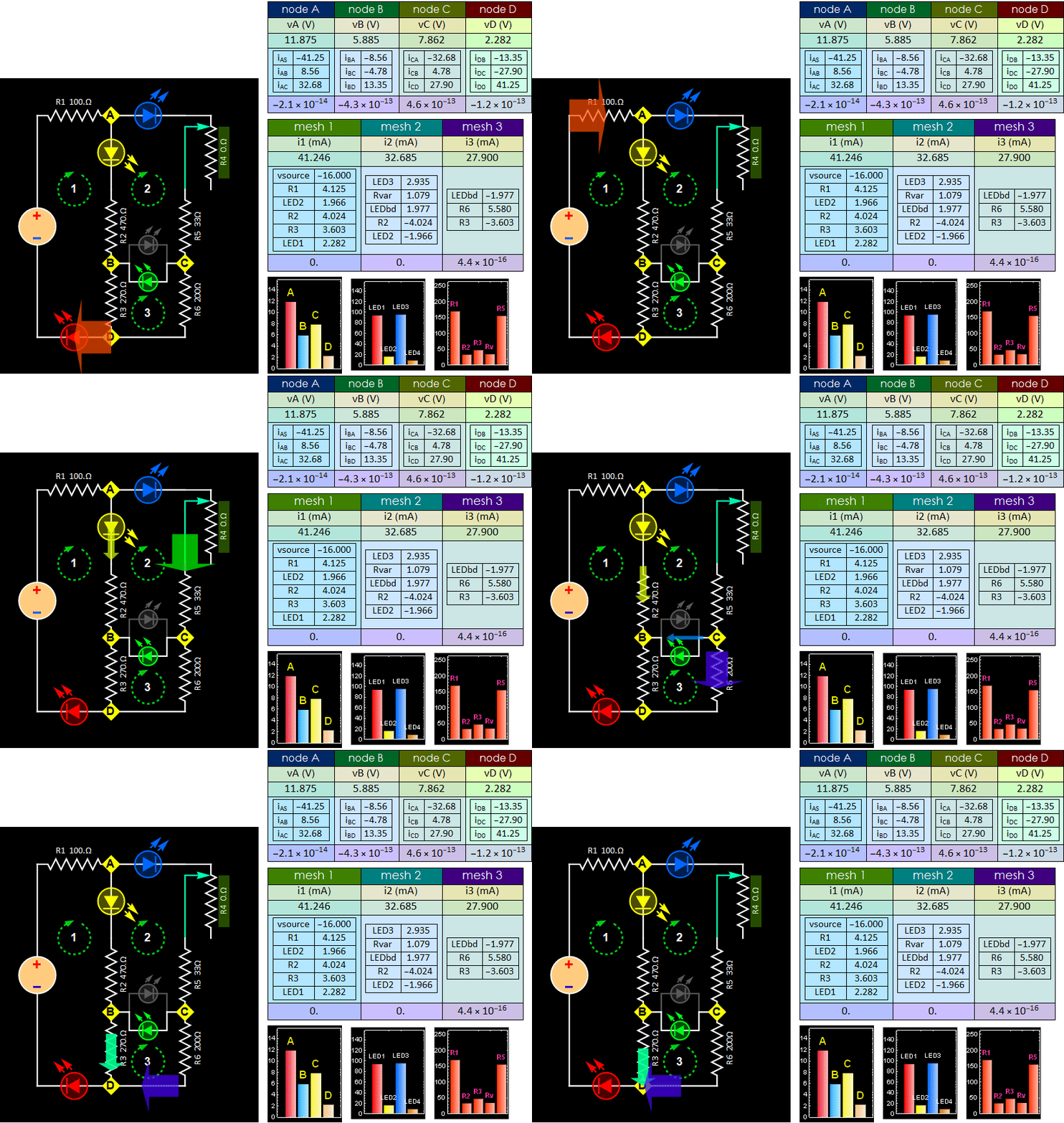
Wheatstone circuit.
Fig. 7

![]()
- Step C1:
With the source voltage off or 0 V,
insert the bidirectional LED in the
circuit you built in Part B. If you have
a real bidirectional LED just insert it
in and don't worry about its polarity.
After you start Step C2 below, if you
set the pot to zero such that LED 3 is
bright, you will see it either amber or
green, depending on the current
direction).
The app
default is that the LED is green for
current flow from C to B. So, if you
see amber color, just flip it around.
However, it doesn't matter
much if you choose amber or green when
node C is higher than B. You can still
do all the measurements below, just make
sure you report that in Lab Notebook.
If you use a
pair of LEDs, you can pick two
different colors of your preference,
as long as you make a note in your Lab
Notebook which color indicates which
direction.
-
Step C2:Turn
the R4 potentiometer to 0 Ohm
position, (If you are not sure which
end is the zero, leave it in
approximately in the middle and
continue). Slowly
turn up the voltage
from 0 to between 11-15 V: as long as
the LEDs are bright enough for you to
see, but do not burn them. Then, turn
the pot one way or another while
observing LED 3 (the blue one in Fig.
7): if it is brightest, that is 0 Ohm
position.
i. Do mesh voltage measurement for all
three meshes. Verify KVL like Step A3
or B3 above.
ii. Measure current i2 (break open R5
and C), i3 (break open C and R6), and
iCB (the current through LED C-B) to
verify KCL: i2=i3 + iCB
- Step C3: Tune
the R4 potentiometer to the maximum
position (opposite to that in C2), you
will see all LEDs become dimmer. If they
are too dim, you can increase the source
voltage a few volts as necessary, just
enough so that LEDs 1 and 2 (red and
yellow in Fig. 7 above - they can be of
difference colors on your own circuit,
your choice) and the LED from B to C
(orange) are bright enough for you to
see, except for LED 3, which can remain
dark and is not important.
i.
Do mesh voltage measurement for all
three meshes. Verify KVL like Step C.2
above.
ii.
Measure current iAB (break open R2 and
B), iBD (break open B and R3), and iBC
(the current through LED B-C) to verify
KCL: iAB=iBD+ iBC
Fig. 8
Tune the R4 potentiometer to observe
LED reversal current increase.

- Step C4: Monitor the voltage between B and C, tune your R4 pot until BC voltage is closest to zero that you can get (it doesn't matter positive or negative, as long as its absolute magnitude is closest to 0). Pull out the bidirectional LED or the LED pair between B anc C, will that make any change to the rest of the circuit? Cite evidences to support your claim. (no changes mean no change of any node voltage or mesh current. You don't need both. Just measure either voltage or current is sufficient to prove change or no change). Visually, all the remaining LEDs will have no visible change. (Hint: if the voltage difference is zero between 2 nodes, whatever passive device you put in there does not change anything to the circuit condition).
- Part D: Discussion,
summary, and conclusion
Report in your Lab Notebook what you think of your study of KVL and KCL of this Lab. Report what you think of each circuit, Circuit 1 (rectifier) and Circuit 2 (LED Wheatstone bridge). Do you think LED is a good indicator of current flow? What else do you learn (personally) by doing this Lab?
END
Continue to appendix