

|
|
ECE 2100 Lab. V -
Capacitors and RC Circuits
Please
download these
items:
1. Lab 5 workbook and report 2. ECE_2100_Lab_5_guide_Part_0 ECE_2100_Lab_5_guide_Part_A ECE_2100_Lab_5_guide_Part_B_C ECE_2100_Lab_5_circuit_simulation |
Please go to update pages for the latest modification, class-wise issues, and others if links for those pages exist.
update page a update page b update page c
| Lab
work modification: TBD
(after class survey and Lab
4) |
Lab work (continued)
Part B
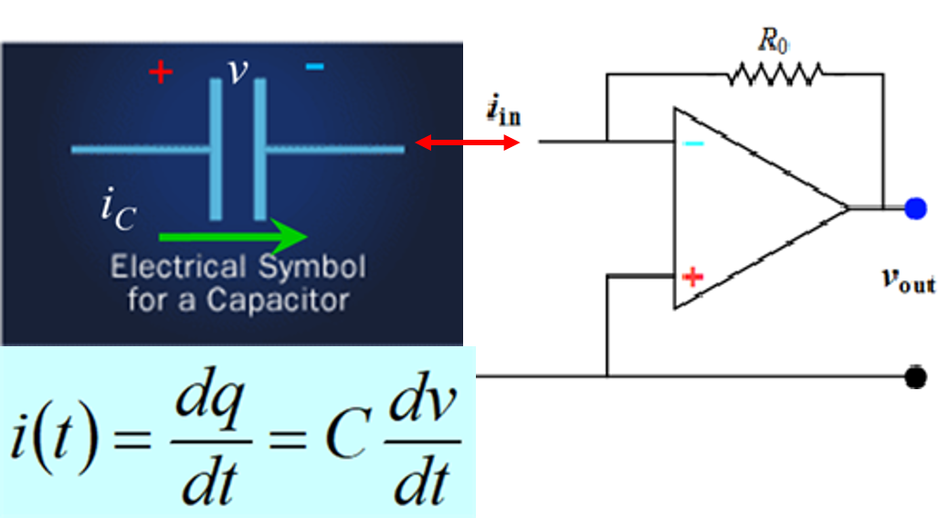
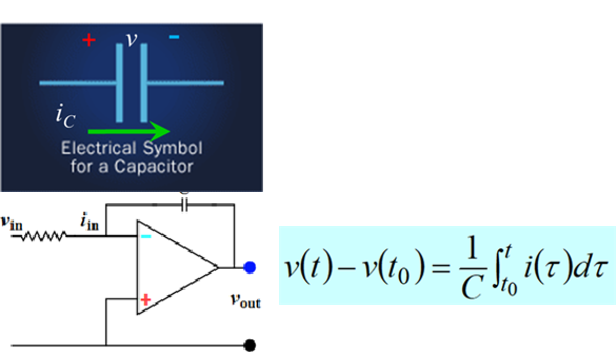
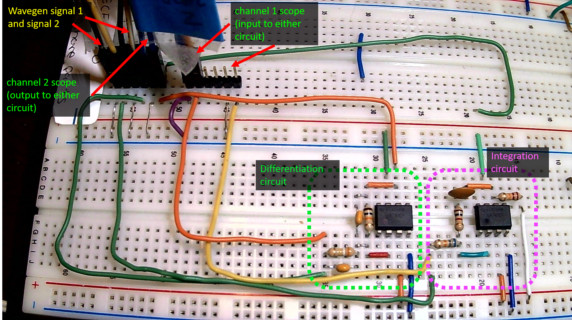
Step 1: Build the op amp differentiation circuit
 |
 |
 |
|
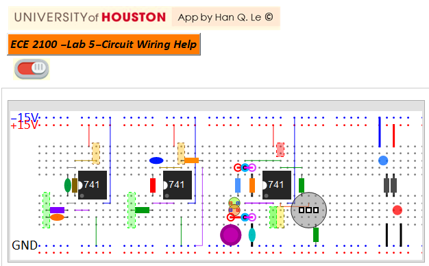
Circuit wiring
Note: if you don't have some components, don't worry. The design of these circuits can be very flexible, because there are more than one way to demonstrate the two basic properties of capacitors. The wiring app below simply shows the default configuration in the circuit simulation app.
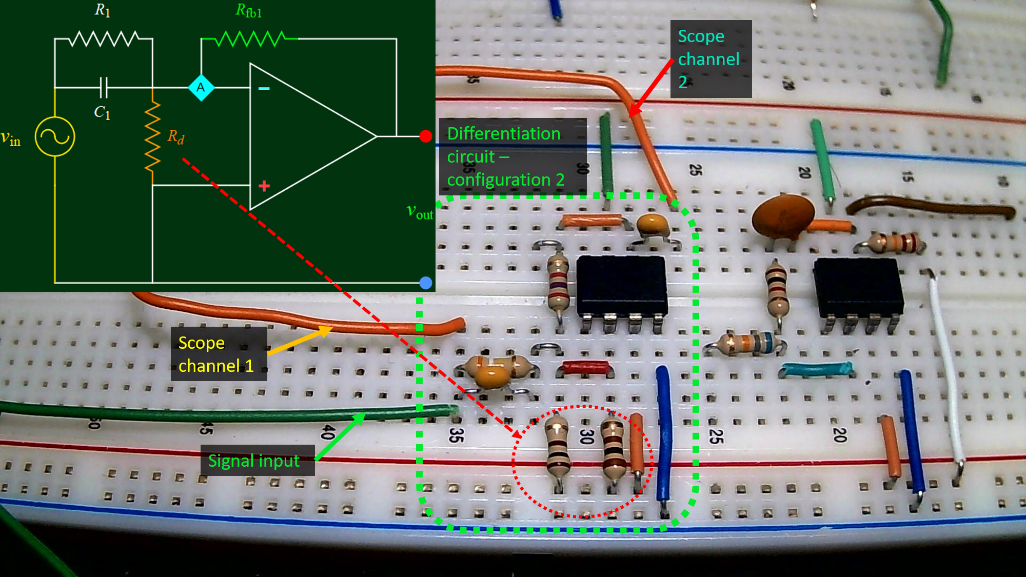
However, you can go further below for an older version of an alternative differentiating circuit. Choose either one most convenient to you.
Alternative circuit: (for those missing some capacitors). Remember: choose only one of the two differentiation circuits (both are quite comparable to each other): either the one in the wiring app, as illustrated by the example above, or the alternative one illustrated in the figure below.
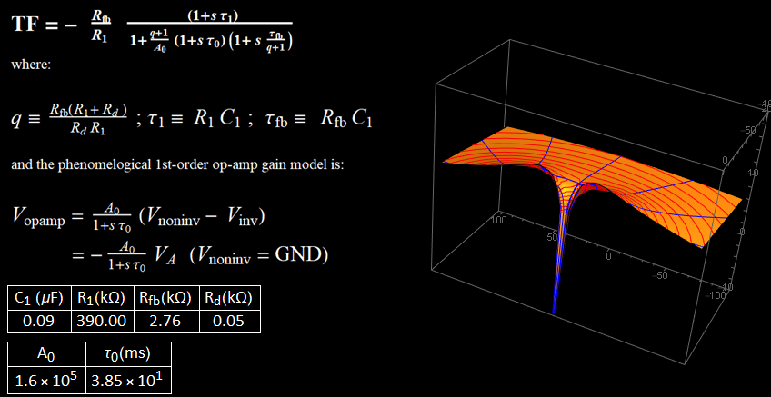
It is not required nor necessary for you to model or calculate the above circuit behavior. For reference, below is a model for its transfer function with the values of the components fitted to an experimental result. Use the following nominal values:
| C1 (uF) |
R1 (kOhm) | Rfb (kOhm) | Rd (Ohm) |
| 0.1 |
100 -
680 |
2.7,
3.3 |
39 - 68 |
| values in the figure
above |
|||
| 0.1 |
390 |
2.7 |
50 (2 parallel
100-Ohm used, because 47 Ohm not
available) |
Below is only FYI. If you have not learned Laplace-transformed circuit and transfer function, just skip the below. If you have, you recognize that s tau is the derivative term, and (1+ s tau) represents a term that is proportional to the signal, known as P term, and term s tau is the derivative of the signal, known as D term. This gives P+D as in PID controller. Go to Update page a for more about this alternative circuit.
3D Transfer Function plot of the alternative differentiation circuit. For the nominal circuit in the wiring App, use the circuit simulation app
Step 2 to Step 5 work plan
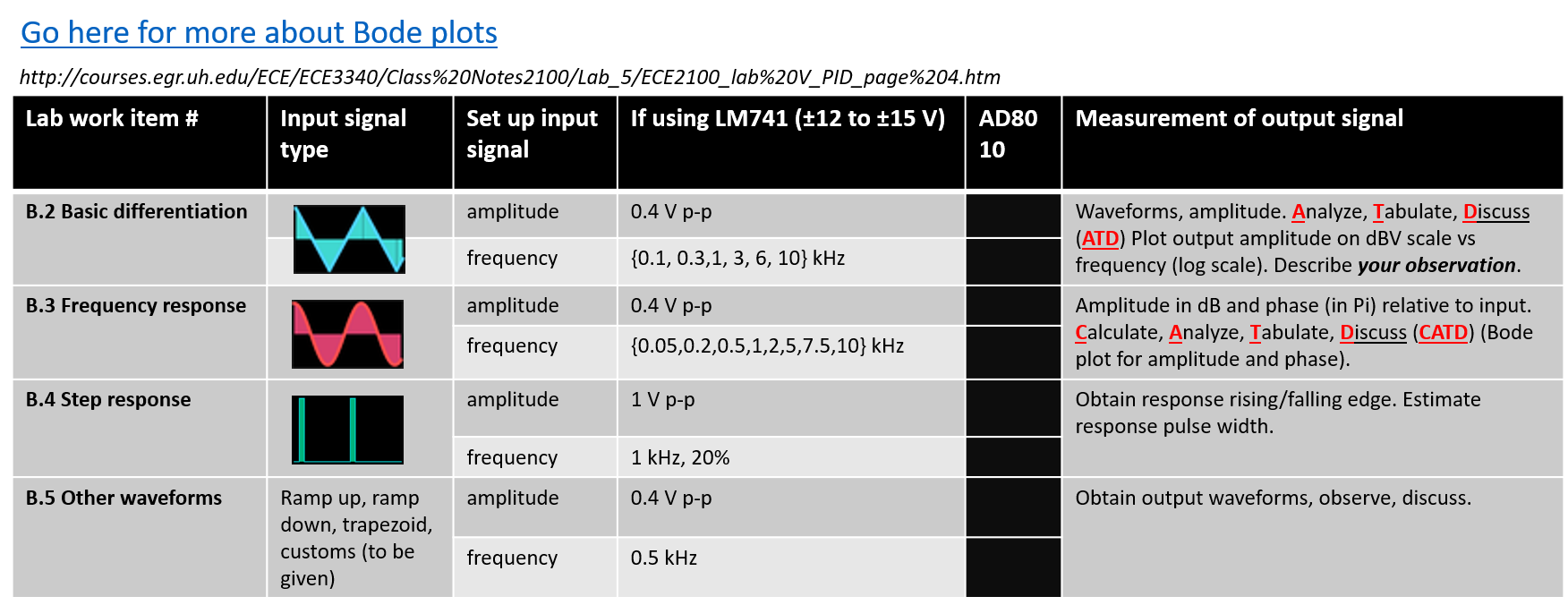
Step 2: Basic differentiation: test with triangle wave input.
The derivative of a linear slope line is a constant. Input a saw tooth (or triangle), expect a square wave.
Please see the video below for details if necessary.
Follow the work plan above to do measurements and analysis.
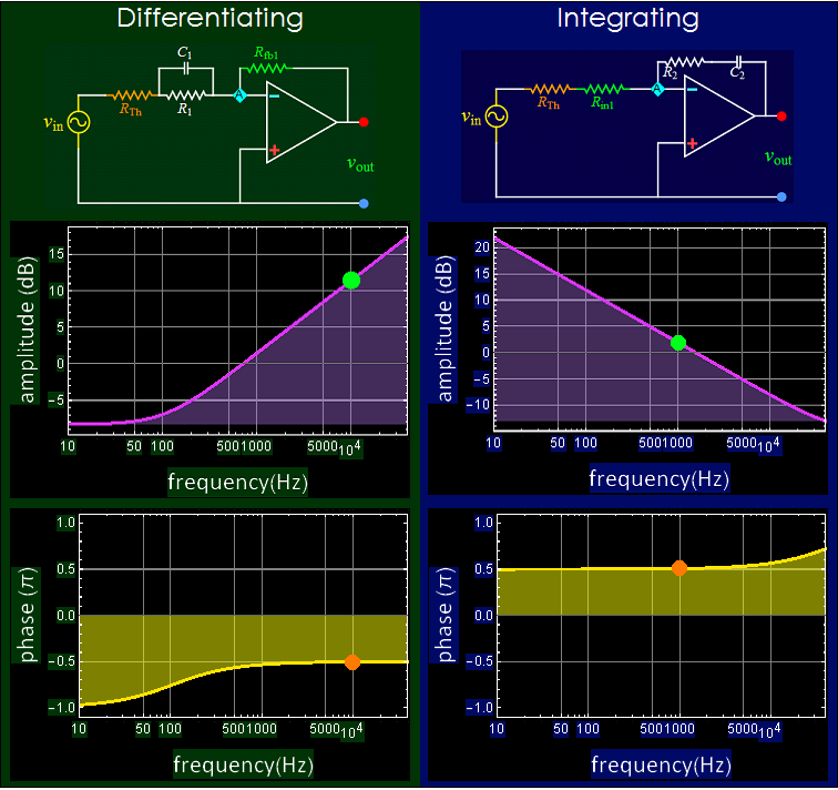
Step 3: Frequency response. Observe the high-pass filtering behavior
Use the circuit simulation app
The Bode plots below are for a circuit with its R, C components having certain nominal values. They are for illustrative purpose only. Use the circuit simulation app
Follow the work plan above to do measurements and analysis.
Step 4: Step response.
Follow the work plan above to do measurements and analysis.
Step 5: Test other waveforms.
Follow the work plan above to do measurements and analysis.
Complete your report with all the evidence of your work, from circuit to measurements, analysis, and multimedia evidence if you provide links. Do NOT embedded large audio-video files in your report. It is your responsibility to ensure that the links to your multimedia files work.
End of Part B
Continue to page 4