
|
|
ECE 2100 Lab. I -
Electrical Measurements,
Serial and Parallel
Circuits.
Please download
the items below:
1. Lab I workbook and report 2. i- ECE 2100 App Lab 1 Part 0 and Part A guide ii- ECE 2100 App Lab 1 Part B guide iii- ECE 2100 App Lab 1 Part C and Part D guide |
| Please
go to update pages for the latest
modification, class-wise issues,
and others - Update page a |
 |
 |
|
 |
Outcomes:
- You will assemble a breadboard that you will use for the rest of the semester.
- You will perform voltage and
current measurements of resistors
and LEDs assembled on the
breadboard.
- You will determine why some breadboard wiring configurations don't work and why some do.
Objectives:
Obviously, the
first objective is for you will
get hands-on experience with
physical items: breadboard,
circuit elements (resistors, LEDs,
wires), and basic circuit
building. It may appear trivial to
someone who is experienced in
electronics. However, the course
does not assume any prior
experience and hence this basic
step is necessary.
The second objective, which is
most essential is to learn how to
measure DC voltage, current,
resistance, and the concept of I-V
curve. To do measurements, we need
circuits, and for this, we choose
the most simplistic but worthwhile
circuit topic: the concept of
serial and parallel circuit
configuration.
Lastly, this may appear a bit
frivolous, but it can be very
helpful for a beginner to learn as
much as possible typical pitfalls
and common errors (i. e. "rookie"
mistakes) in breadboard circuit
wiring. Learning these mistakes
can help one save a lot of time
and hassle later. Hence, you will
construct some circuits that work
and some don't, and try to figure
out the reasons.
Lab instrumentation basics:
- Recommended
tools and instruments
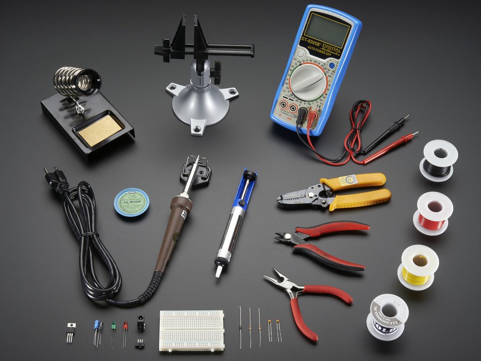
Although not
required, it is convenient to have some
basic basic electronic tools:
needle-nose pliers, wire-cutters, small
screw-drivers, and tweezers. These will
be discussed in class. Below is just a
representative image of common toolkit,
many items shown there are not needed
for the course because we won't do any
soldering, unless you wish do something
special and extra for credits. One item
not required but very handy not just for
the course but general home use is the
small portable digital multimeter (DMM)
(the blue instrument). Most low-cost
DMM's do not have the precision and
accuracy that our lab-bench instruments
do. Hence, you still need to do critical
measurements in the lab. However, with a
DMM, you can at least test your circuit
at home to know that the circuit is
correctly built, and you only need to
obtain more accurate and precise figures
in the Lab with the bench instruments.
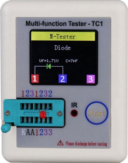
Lo-cost DMM's can test only basic resistance and diode polarity, but not other common circuit elements and properties, such as capacitor, diode/LED forward voltage and capacitance, transistors. For the electronic hobbyist of you, there are simple instruments such as the one below that can be handy for those circuit elements.
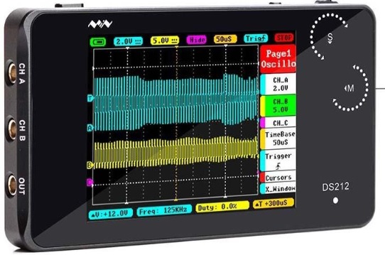
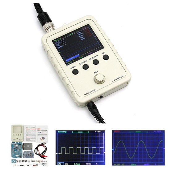
Another must-have instrument for the home hobbyist is an oscilloscope (You don't need for the course). However, if you are really into electronics, there are many highly affordable and acceptable basic oscilloscope kits like the two shown below (both have 1-MHz analog bandwidth and hence, good enough for audio as well as most robotic control applications). For Lab IV to Lab VI of this course, we will study AC signals, hence if you want to test out your circuit at home, thing like the ones below will be quite handy.
- Breadboard
assembly
Assemble the binding
posts on the circuit breadboard as
illustrated below.
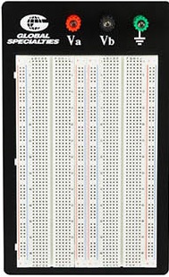
Note that you can
choose either convention with the black
post for the ground and the green post
for Vb or vice versa. However, if you
choose the convention like that in the
picture, it will be consistent with your
power supply (green for ground) and
perhaps it will reduce risk of wrong
connection when you build circuits with
op amps (Lab IV to Lab V).
Make sure the nuts
on the binding posts are well tightened
to avoid loosening the posts when making
wire connection.
- Breadboard
instruction
- Lab-bench
instruments
Lastly, two most essential instruments on your bench are:
- the DC power
supply (click on image for pdf manual):
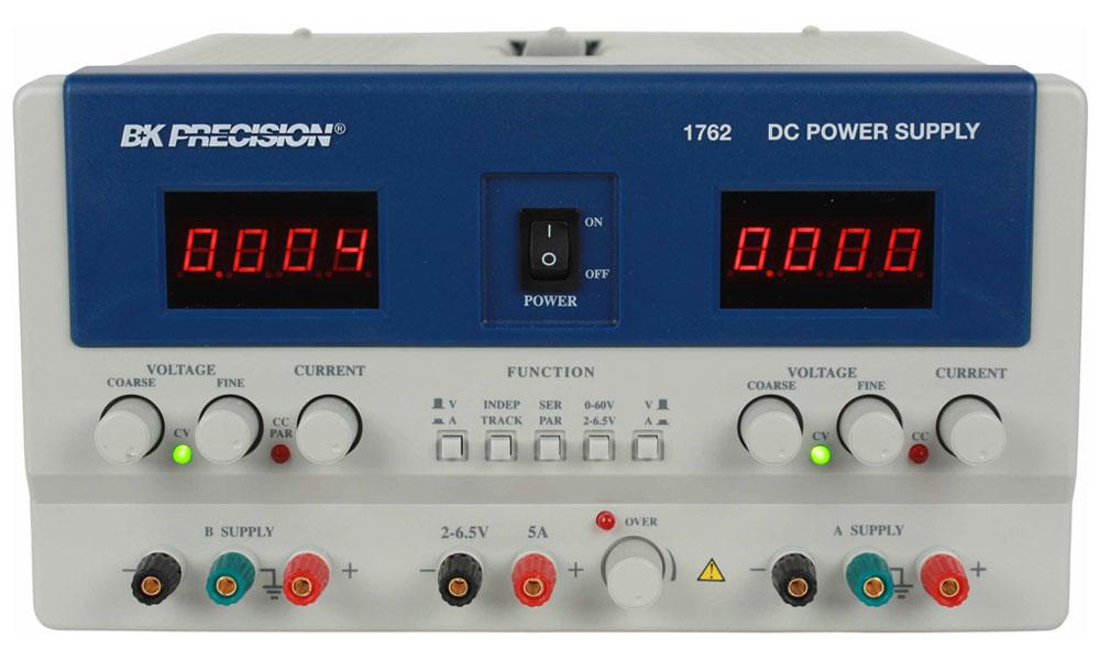
some video
instruction: at
this link. 
At this stage, we
don't need +/-15 V yet for op amp power
supply, but the video below is a good
reference for future use:
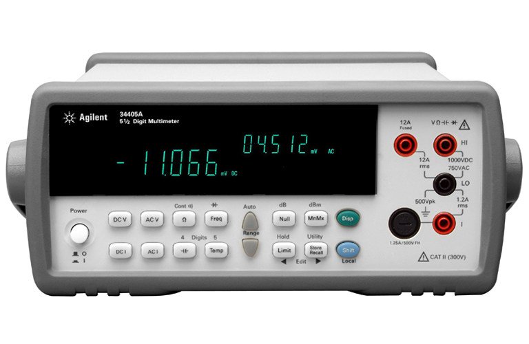
- the digital multimeter (click on image for pdf manual):
Unfortunately, this product is obsolete and lacks many features that its replacement models offer, such as web-browser html access and control. Nevertheless, it is still adequate for what we do in this course.
We will discuss and
do demo of these two pieces of equipment
in the class lecture. You are strongly
encouraged to search any online
instructions beside the manuals.