
|
|
ECE 2100 Lab. I -
Electrical Measurements,
Serial and Parallel
Circuits.
Update - page a |
Important note:
Note about using batteries or home-based power supplies:
Also, consider using discarded AC/DC adapters. Just cut-off the end connector and wire with banana plugs or alternatives.
Lab work modification:
1- All Parts and Steps: If you cannot measure a current, it is fine. If it involves the current with a LED, and a current change is required, just show pictures, or state your observation of the LED variation in brightness as evidence of the current change.
2- For Part B-Step 4:
Question 2: it is OK to do modification as
shown below:
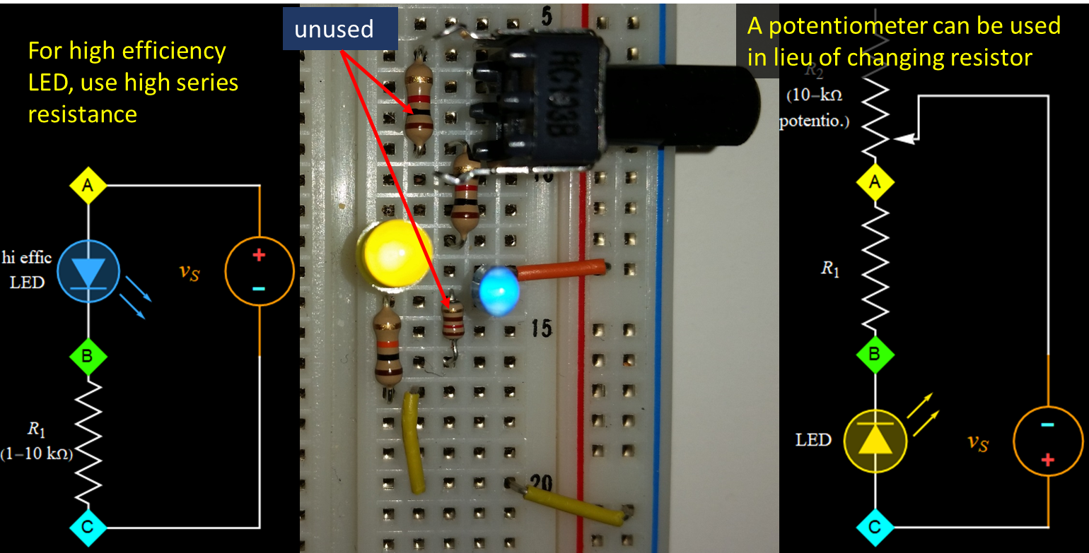
-2.a If you have high
efficiency LED that is very bright with
low current (few mA), you can use the load
series resistance in the range of kOhm,
not 100's Ohm. Example, for the blue and
yellow ones below, each has a 10-kOhm and
1-kOhm resistor, respectively, because
they would blind the webcam with higher
current (although not the cell phone cam
below). At home, you can use whichever
value so that a LED brightness is
acceptable to your eye, usually in the
range from few mA - 20 mA (or even more if
for the typical red and green LED). It
also depends on the camera you use to take
picture and paste in the report. The exact
resistor value is not important,
especially if you cannot measure the
current anyway; just report the resistance
value you use.
-2.b If you know how to
use a potentiometer (go to Lab 2, Part B
for a description how to use it), instead
of pulling the series resistor out and
replacing it with different resistors of
increasing resistance, you can just tune
the pot from 0 to 10 kOhm, which should be
in series with another resistor as shown
in the right-hand-side schematic (1 kOhm in the picture).
Just demonstrate that the LED is dimmer if
you increase the potentiometer resistance.
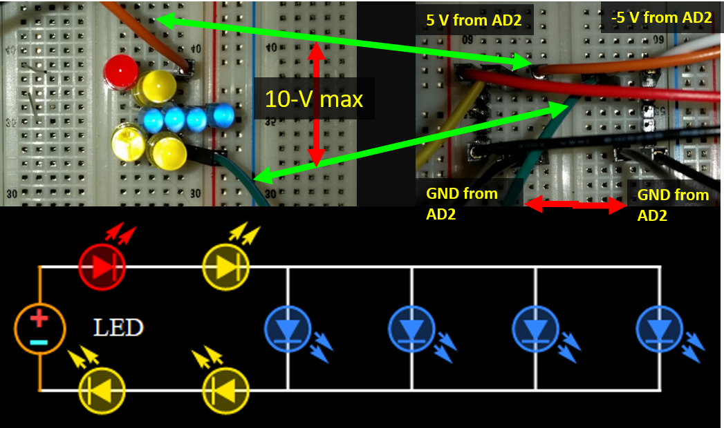
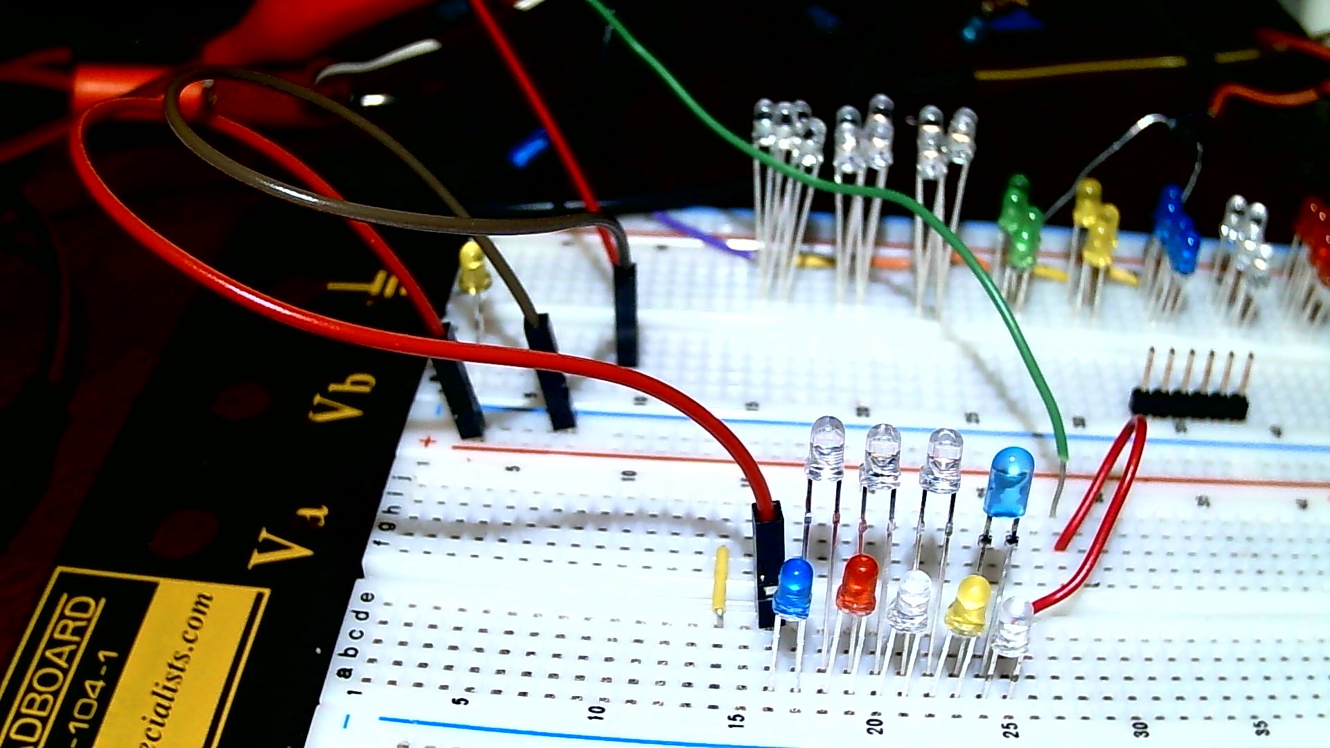
3- For Part
C-Step 3: You can build a circuit
that combines both serial and parallel
LEDs as shown below and will be accepted
as both circuits (IOW, one is counted as
two). If you build two separate circuits
with more than 5 LEDs in each, you will
get extra credits. (however, 10 V will be
enough only for 5 LEDs in series. For
parallel, of course, one can have
practically as many LEDs as one can afford
as the AD2 can give ~700 mA).
More serial & parallel: 15 V
can drive at most 6 serial LEDs of mixed
color with a little margin, and barely
with 7. See below
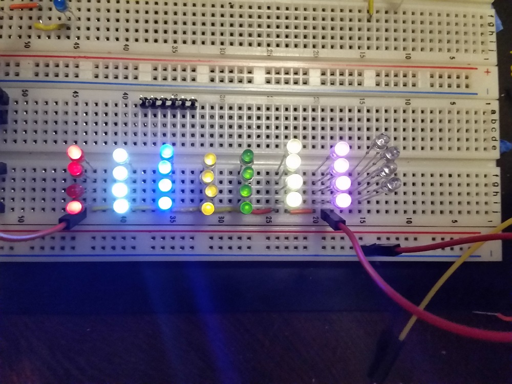
Yellow and green are barely
visible.
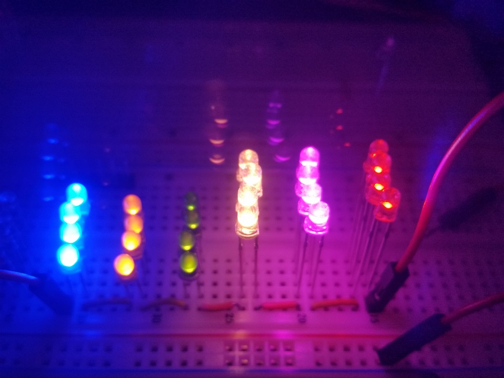
Without the red and white on the
left, the pink and orange (right most) are
actually bright, but not obvious with
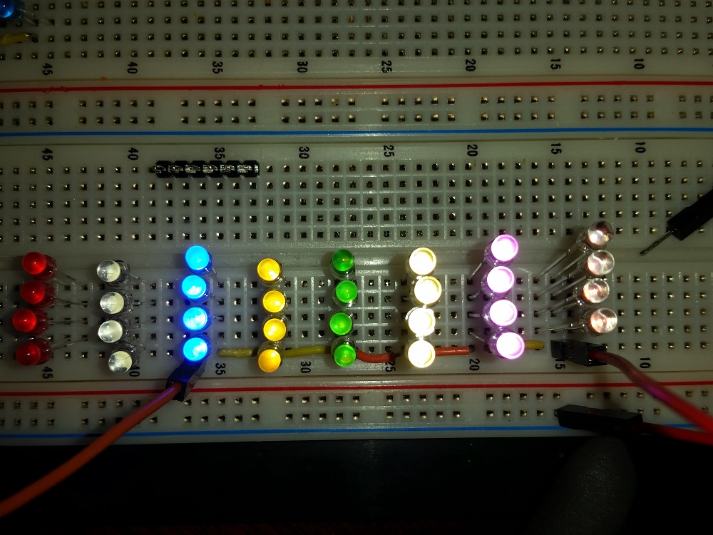
strong camera flash. Below are without
flash. The right most LEDs are actually
orange to the eye, not reddish.
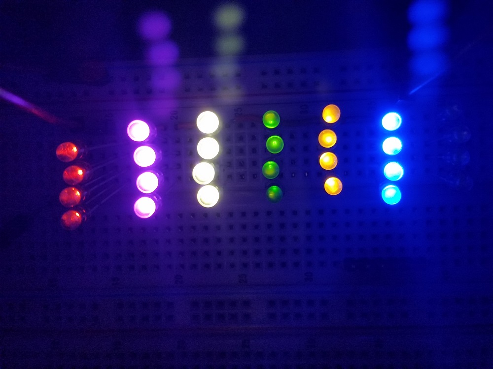
Attenuated with another neutral density
filter, the right most are orange, not
red.
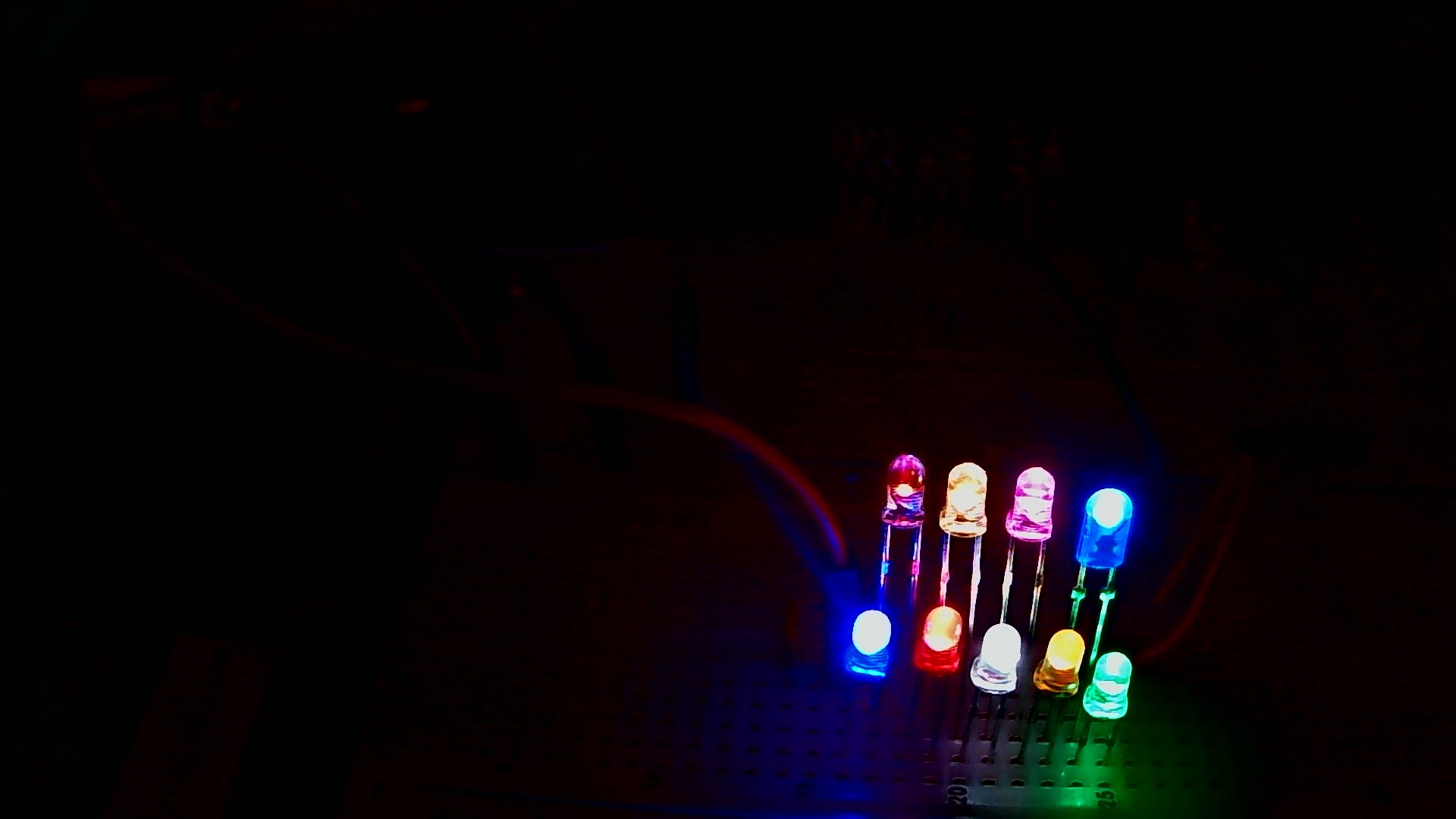
21.5 Volt can drive 9 mixed color LEDs
with high brightness. It can do 10 with
lower band gap LEDs (red, orange)
 |
 |