
|
|
ECE 2100 |
Lab
Work (continued)
- Part D: Serial and parallel concept
What are the
functions or applications of
electrical circuits?
For virtually
all of them, there are three major
applications:
- power distribution,
- signal/information processing (communication/computing), and
- control (related to signal processing).
Consider the simplest power distribution application that we all are familiar with:
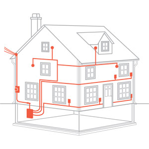
The household circuit is designed
to distribute the power from the
street or electrical pole to
appliances in the house. The
appliances should be independent
from each other, hence, each is
directly wired to the power
source, resulting in parallel
configuration. An essence of
the parallel configuration power
distribution is that it must be a
voltage source, which supplies
variable current to the demands,
up to the maximum current capacity.
A circuit short can take up the
entire current capacity, and all
other appliances will fail.
An analogy of
parallel circuit is the water
distribution system to the home:
Every
household has the same
pressure, but the water
flow rate can vary
depending on usage.
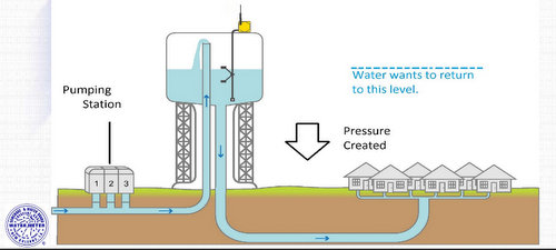
The
opposite of parallel configuration
is the serial configuration.
Consider another analogy:

Assume for
simplicity that a river
volume is conserved over its
course (neglecting minor water
adding and subtraction from small
tributary streams and rivulets),
then the water pressure or
potential energy can vary over
different segments as illustrated
above, but the flow rate is the
same (water mass conservation). If
each dam produces hydroelectricity
with identical turbine system for
all dams using the same water flow
rate, the power output would be
different depending on the
pressure differential (water
potential energy) at each dam.
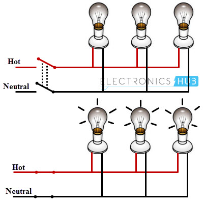
In the old
time, we sometimes see serial
circuits such as the one below:
The
advantage of this
configuration is that a
small current (low risk of
fire) can be used with
high voltage to supply the
power. The disadvantage is
well known: if
a light is broken (open) or
removed, it breaks the current and
the entire circuit is off. But if
a light is shorted, the circuit is
still working.
For Part D, we
will study two very simple
examples below:
Fig. 4.1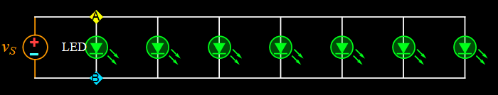 |
All LED's should be
of the same color. If you are short
of LEDs of the same color, you can
mix LEDs of very close colors, such
as mixed red/orange, or mixed
yellow/green. Blue cannot be mixed
with any other color (unless you
have purple). The circuit is
scalable, the number of LED's can
range from 4 - 8 depending on how
many you have. |
Fig. 4.2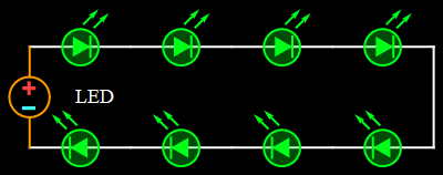 |
Same as above with
regard to LED color. |
To implement
circuits in Fig. 4.1 and 4.2 onto
a breadboard, consider Fig. 4.3
below.
Fig. 4.3
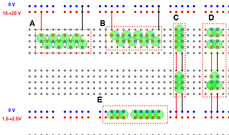
Figure 4.3
above shows 5 wiring
configurations of group of LED's,
labeled A, B, C, D, E. The last
block, configuration E, is the
obvious diagram of 8 LEDs in
parallel. It is shown only for
illustration. For the Lab work of
Part D:
- determine
which of A, B, C, D LED blocks
represents the circuit in Fig. 4.2
- build the circuit, apply the
voltage while monitoring the
current until the current is 15±1
mA. (if your LEDs are too dim,
raise the current to the level you
feel sufficient to see).
- measure the voltage and obtain
the total power (P= V x I).
Divide the total power by the
number of LEDs to determine the
average power per LED.
- determine which
of A, B, C, D LED blocks
represents the circuit in
Fig. 4.1
- build the
circuit, apply the
voltage while
monitoring the
current until the
current is n*15±1
mA where n is the
number of
LEDs. For
example, if n=7,
the current should
be 7*15 mA=105±5 mA.
-
measure the
voltage and obtain
the total power
(P= V x I).
Divide the total
power by the
number of LEDs to
determine the
average power per
LED.
- compare
the per-LED power
of circuit 4.2 and
circuit 4.1.
Discuss.
- discuss
what's wrong with
the other circuits
that are not
selected for
measurement.
- Part E: Parallel current distribution
Fig.5.1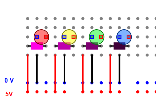 |
Consider the circuit
in Fig. 5.1. The 4 LEDs should be
red, yellow, green, blue. The
resistors are of your choice such
that the current in each LED should
be approximately 15 ± 5 mA.
(depending on your LED type, you can
go higher or lower, as long as it is
safely below the damage threshold of
the LEDs - check with manufacturer's
specs). Use the app in Section 3
(Part C) to get an estimate for the
resistance value for each LED. Use
resistors in parallel if necessary
to obtain the value you need. Work to be done and reported: - draw the entire circuit schematic with measured resistance values (after selecting appropriate resistors) - measure the current of each LED circuit, which should be 15 ± 5 mA as indicated above - measure the voltage of each LED - measure the net current supplied by the voltage source (nothing else should be connected to the voltage source besides this circuit). Verify if the measured net current is equal to the sum of all LED currents. |
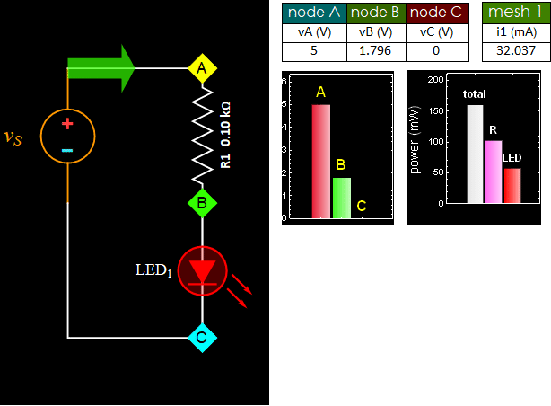
Hint: see the
figure below. The calculation uses
a fixed value of R1 for all LED
colors. Hence, it is up to you to
find and match the resistance for
each LED color such that the
current is as close to 15 mA as
possible.
![]()
END