|
|
ECE 2100 Lab. I -
Electrical Measurements,
Serial and Parallel
Circuits.
Appendix - page i |
How
to measure I-V curve for the LED
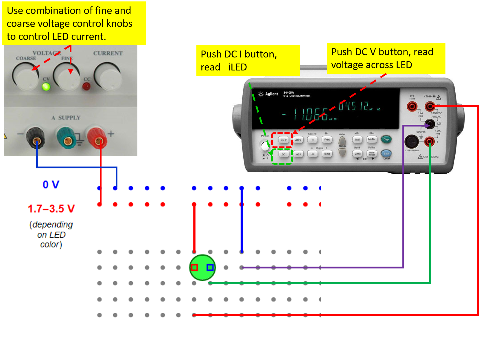
In the configuration below, the measured voltage is directly across the LED, but the current probe polarity is reverse of that of the LED and you will read a negative value. Just flip the sign. This is how you vary the current:
1- push the DC I button.
2- vary the coarse and fine voltage power supply knob to read approximately the current value you want. No need to be precise. For example. you want to set 10 mA, it is OK to get anything from 7 mA to 13 mA.
3- push the DC V button and read the voltage. If the Auto scale is not on, just push its button.
It is recommended that you use hook connectors and avoid hooking the connector onto the LED leg. Use a short wire with one end plugged into a hole and the other end for the connector. That way, you don't touch the LED throughout the measurement process.
This
is an example what you
should record in your lab
notebook:
| current (mA) |
voltage (V) |
| 0. |
0.5 |
| 0. |
1.5 |
| 4.211 |
1.653 |
| 12.75 |
1.771 |
| 19.3 |
and so on... |
and so
on... do it
for current from 0 to ~30
- 35 mA. You can go to 50
mA for red, orange, yellow
if you wish. Do not go
much more above 30 mA for
the 480-nm blue LED. If
you really want stable and
low-error measurements,
you can short the two
leads of current
measurement together each
time you measure the
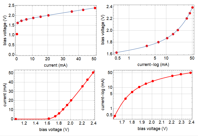
voltage. Below is an
example of a red LED
distributed to the class.
The points are data and
the curves are model fit.
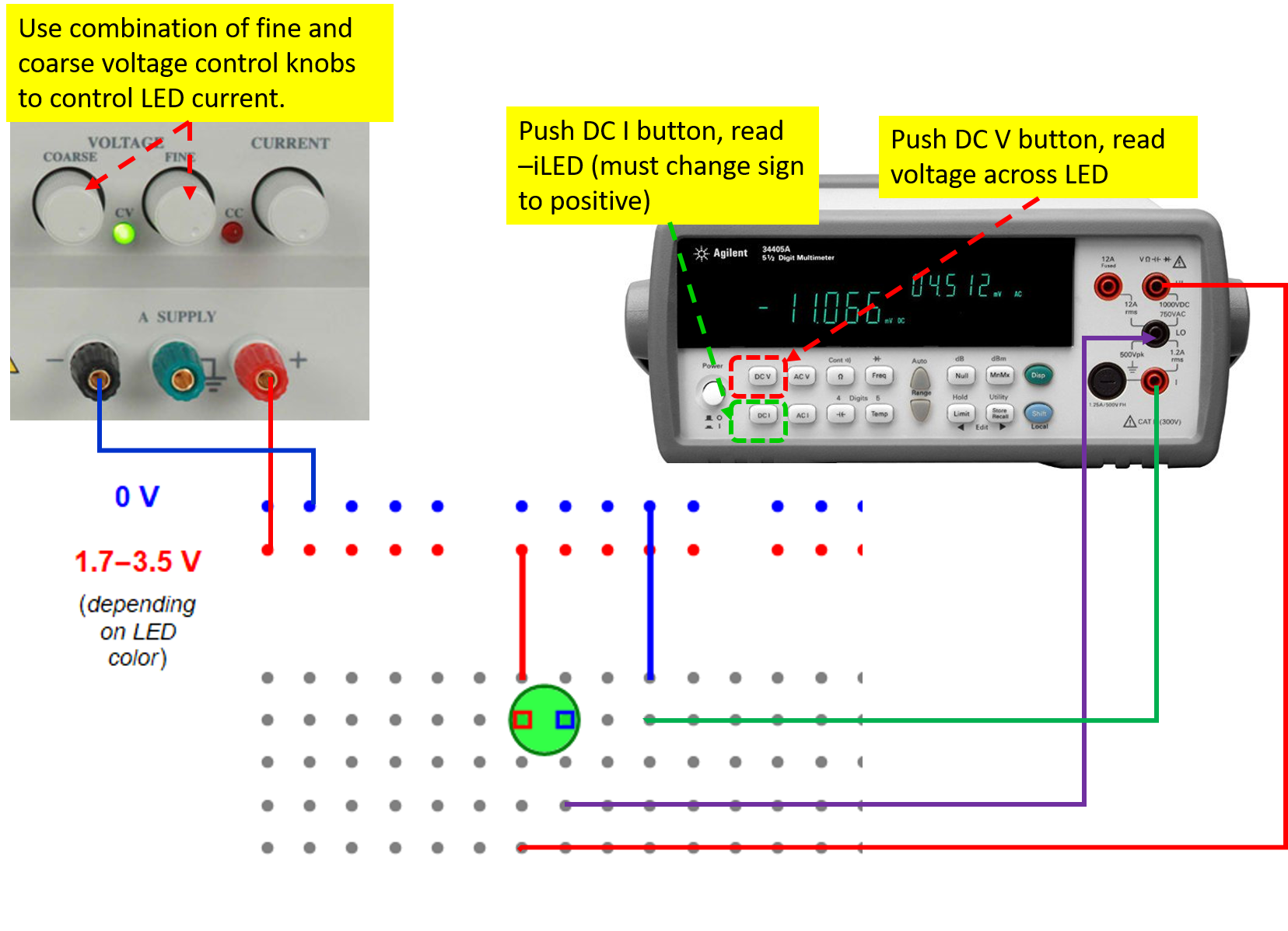
If you wish to see both
positive sign for voltage
and current, use the
configuration below.
In the
configuration below, the voltage
is measured across the LED and the
current probe of which the
impedance is negligible and hence
its voltage is also negligible. In
this case, both the voltage and
current will have positive sign.
Read the steps above to set the
current, read voltage and record
in your lab notebook.