

|
|
ECE 2100 Lab. IV -
Dependent Sources -
Operational Amplifier
Voltage Amplifier, Transimpedance Amplifier Please
download these
items:
1. Lab 4 workbook and report 2. ECE_2100_Lab_4_guide_Part_0 ECE_2100_Lab_4_guide_Part_1 Special guide: ECE_2100_Lab_4_CircB_wiring_guide Special guide: ECE_2100_Lab_4_Part_1_Step_5_AD2_guide ECE_2100_Lab_4_guide_Part_A ECE_2100_Lab_4_guide_Part_B and C see demonstration and write a report only) |
Update page b
|
Lab work modification: - Do Part 0 ( Introduction), Part 1 (Instrumentation), and Part A only (three parts total): do everything, including answering/discussion all questions.- Experimental work of Part B and C are not required: It means no circuit, no measurement needs be done. You are required to only observe and write a report of your understanding, thoughts, and summary of these Parts. This should be put at the end of your report, a synthesis of everything that you learn in Lab 4. Create a subsection, titled "Report on observation of Parts B and C demonstrations". Do not mix this with what you summarize for your work in Part A. However, if you do any work along the line of Part B and Part C, you are welcome to include for extra credit. |
Part B and Part C online reference
Below are html excerpts from ECE_2100_Lab_4_guide_Part_B
and C ![]()
Introduction to Part B and Part C
Part B - Step 1
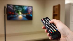
remote control
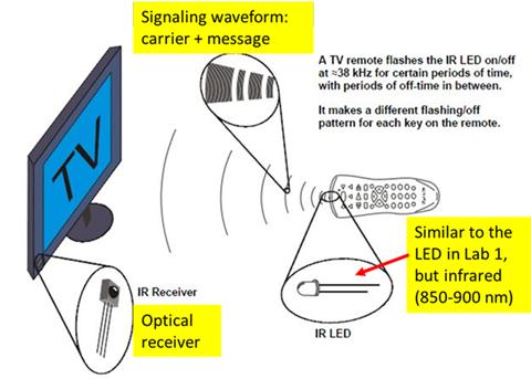
remote control system concept
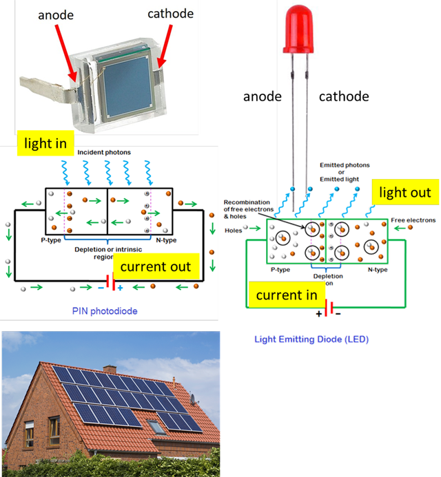
photodiode vs LED
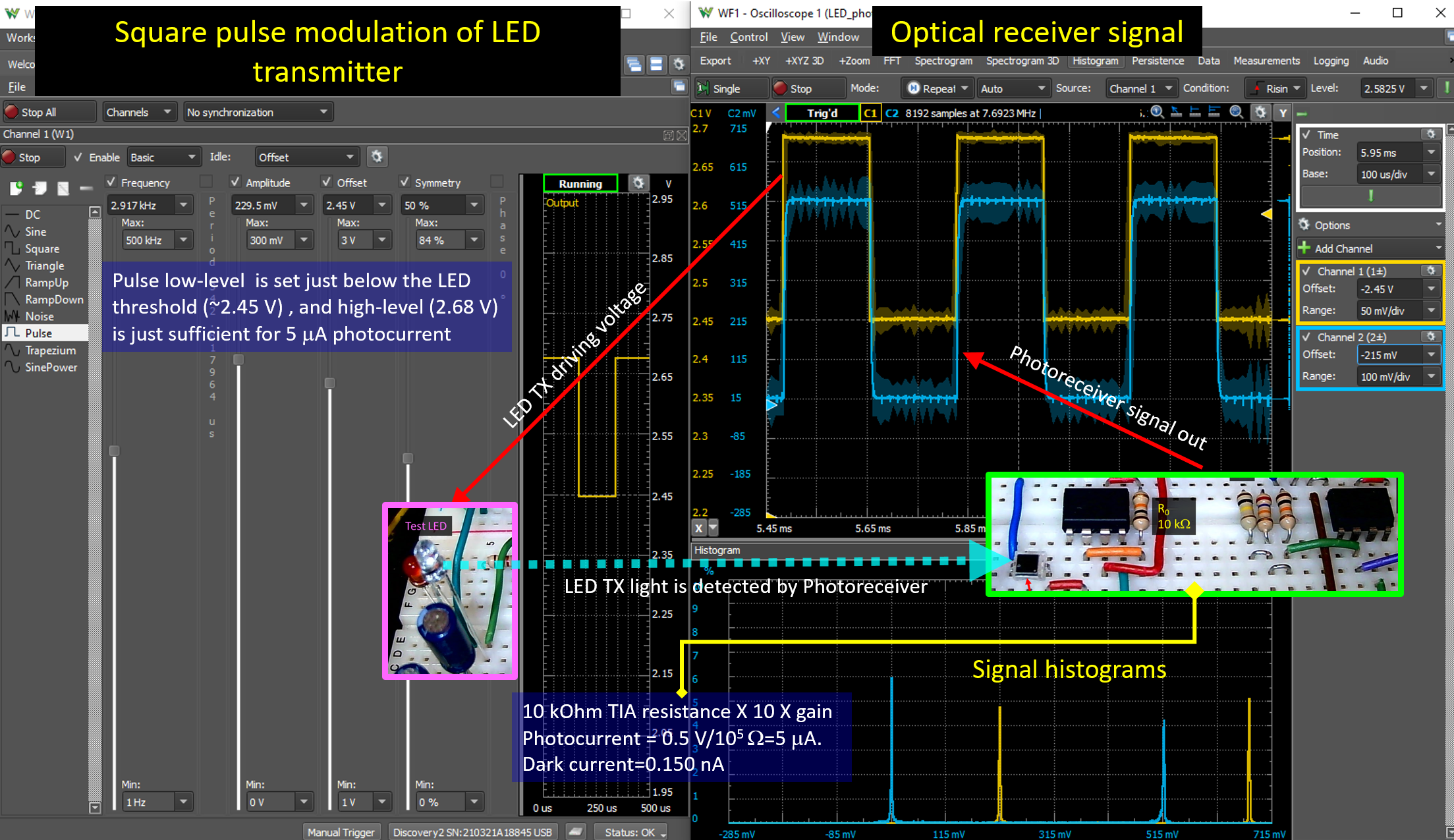
TIA basic concept
Part B - Step 2
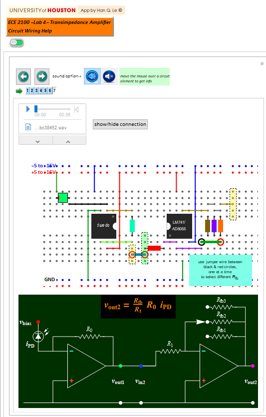
wiring diagram for photoreceiver
Please use the app in Mathematica for step-by-step instruction
Part B - Step 3
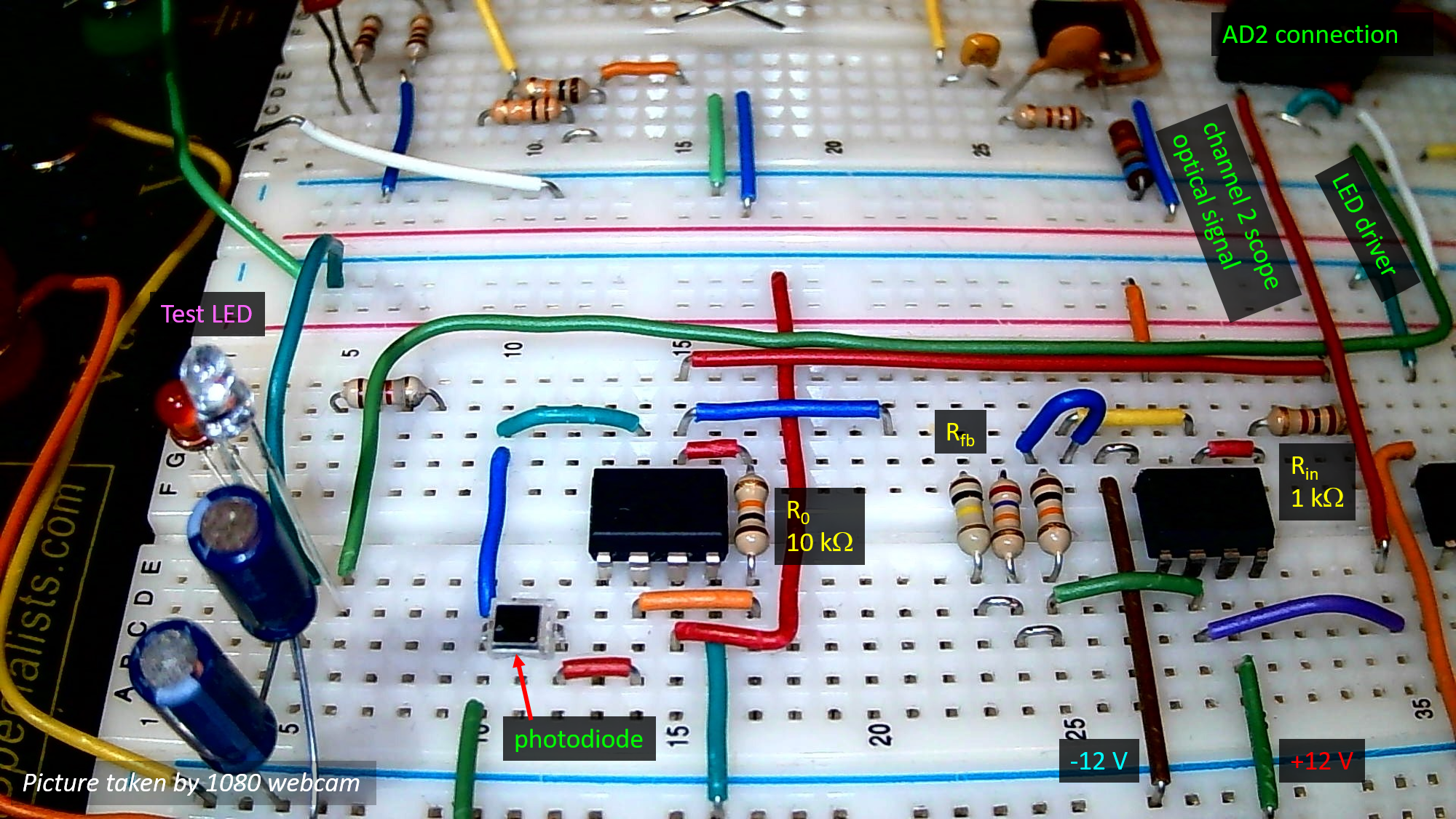
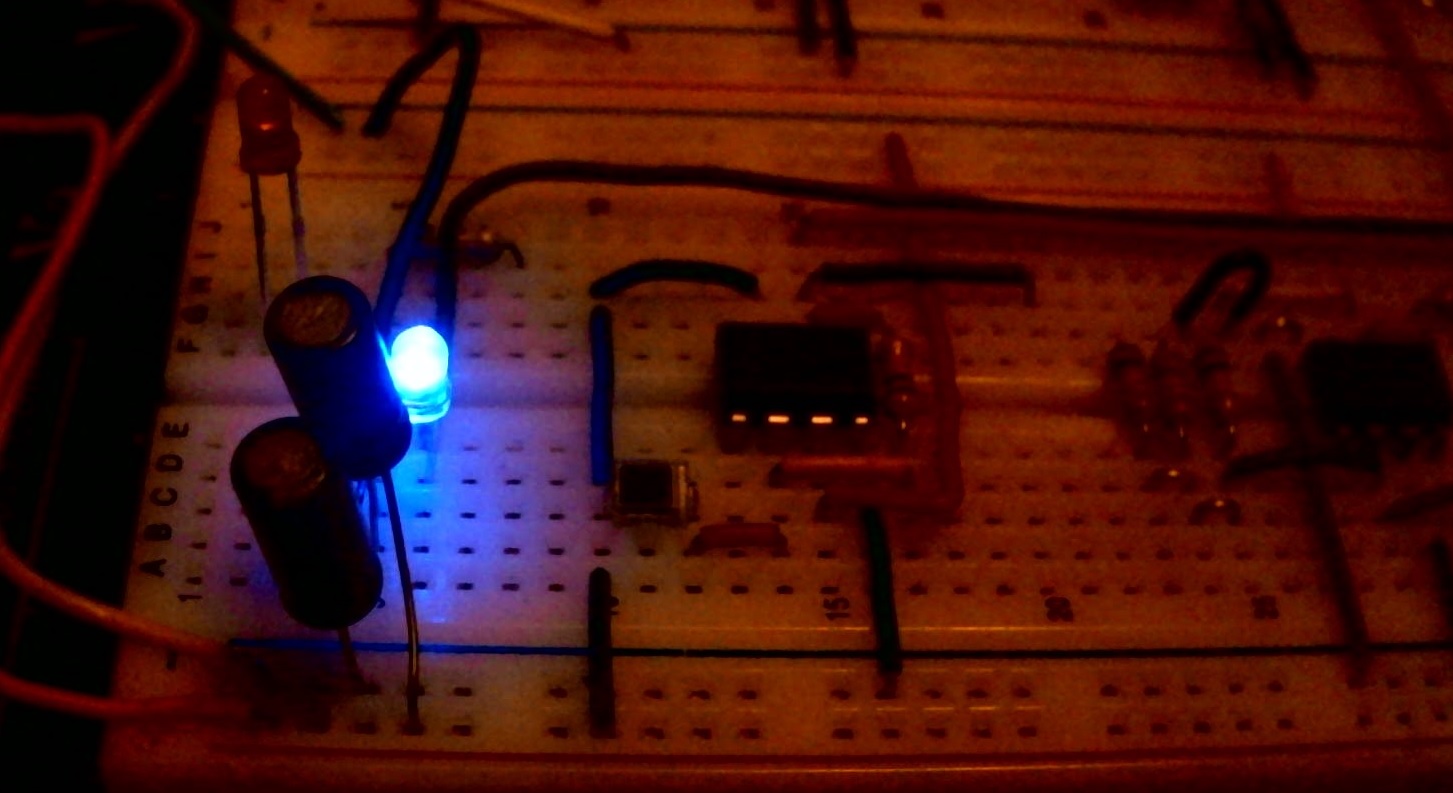
Example of the circuit (click for full size)
click both the audio and the video below
Lab4 3-dB bandwidth demo
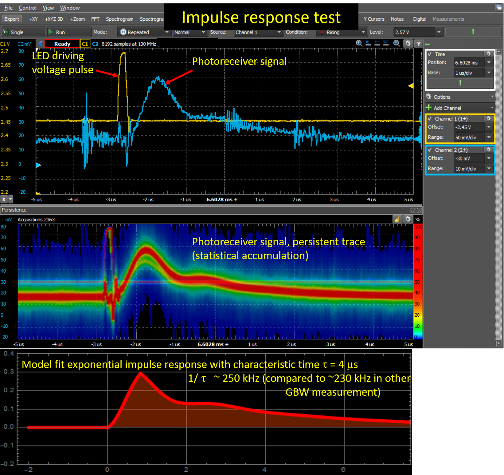
impulse response test
End of Part B
continue to Part C