

|
|
ECE 2100 Lab. IV -
Dependent Sources -
Operational Amplifier
Voltage Amplifier, Transimpedance Amplifier Please
download these
items:
1. Lab 4 workbook and report 2. ECE_2100_Lab_4_guide_Part_0 ECE_2100_Lab_4_guide_Part_1 Special guide: ECE_2100_Lab_4_CircB_wiring_guide Special guide: ECE_2100_Lab_4_Part_1_Step_5_AD2_guide ECE_2100_Lab_4_guide_Part_A ECE_2100_Lab_4_guide_Part_B and C see demonstration and write a report only) |
Page 1
Important: Digilent AD2 - a note
Please go to update pages for the latest modification, class-wise issues, and others if links for those pages exist.
update page a update page b update page c
Lab work modification: - Do Part 0 ( Introduction), Part 1 (Instrumentation), and Part A only (three parts total): do everything, including answering/discussion all questions.- Experimental work of Part B and C are not required: It means no circuit, no measurement needs be done. You are required to only observe and write a report of your understanding, thoughts, and summary of these Parts. This should be put at the end of your report, a synthesis of everything that you learn in Lab 4. Create a subsection, titled "Report on observation of Parts B and C demonstrations". Do not mix this with what you summarize for your work in Part A. However, if you do any work along the line of Part B and Part C, you are welcome to include for extra credit. |
Outcomes:
-
You will demonstrate a simple
signal amplifier and an optical
sensor that can be used for many
applications, such as remote
control, robotics, or
general-purpose light-level sensing
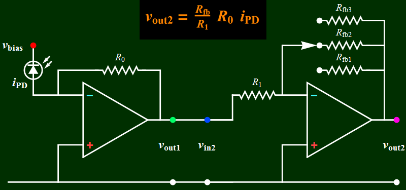
- You will build the circuits below. Circuit B is a voltage amplifier that accepts an input voltage signal and yields a proportional voltage output. Circuit A converts the input current from a photodiode (a light sensor) into a proportional voltage output. It is also known as a transimpedance amplifier.
- Circuit B will be built first
and tested. Once it is shown to
function as intended, circuit A
output will be the input of circuit
B to make an optical
sensor/receiver.
| Circuit
A |
Circuit
B |
 |
 |
| Both Circuit A and B joined
together to form a single device: optical
receiver (detector) |
 For an optical
sensor, the gain on B is adjusted
to the light signal level. Low
gain for strong signal, such as
the light from a modulated LED
placed near the diode. High gain
for low light level such as
scattered room light through an
opening on the cover of a shielded
diode. A remote control can be
tested from a distance and high
gain can be used to test the
optical detector sensitivity.
|
Objectives:
You will learn and experiment with dependent sources, using operational amplifier - or “op amp” for short. Specifically, the op amp will be used as a dependent voltage source of which the output depends on:
a. an input AC voltage signal from an instrument (a signal generator), or a sensor (the photodiode of circuit A); this is the case for circuit B; or
b. an input current signal source which is from a photodiode; this is the case for circuit A
Introduction
and background:
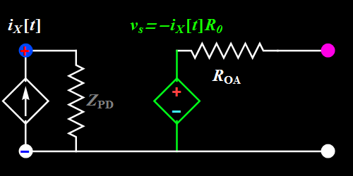
Please review your ECE2202 lecture as necessary on op amp and various op-amp circuits (note: This course is a lab course, hence we do not have time to go through the detailed circuit theory background. This page provides the minimum information you need to do the lab). The only knowledge that you need for this lab is the equivalent linear circuit models shown below.
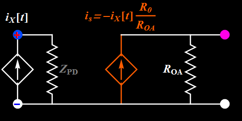
| Circuit A Note that the
time-varying nature of the input
signal current is explicitly shown
as a function of time.
|
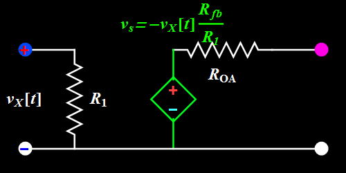
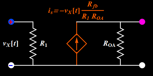
Circuit B Note that the
time-varying nature of the input
signal voltage is explicitly shown
as a function of time.
|
| Thevenin equivalent
circuit |
Thevenin equivalent circuit |
 |
 |
| Norton equivalent circuit | Norton equivalent circuit |
 |
 |
Let's take a look at Circuit B. How does it work?
Basic illustration
 |
| The left hand side
shows a sinusoidal signal input. The
right hand side shows the output
from the dependent source. The
output signal looks every way like
the input except for the amplitude.
Here, it is larger and we call it
"amplification". If it is smaller,
we would call it "attenuation". However, we can use the concept of amplification for both cases. We define that gain or amplification factor as the ratio of the output amplitude relative to that of the input. This includes both real amplification and attenuation. |
So far so good. However, does the circuit truly work like the ideal formula above? We can find out by increasing the input signal amplitude.
Topic 1: Amplitude saturation
 |
| At first, the circuit
works as expected. We increase the
input signal amplitude and the
output amplitude increases
proportionally. But does it increase without limit? There is no such a thing as infinite amplitude. Every source has finite amplitude and for our op-amp voltage amplifier, as it is biased with +- 15 V, we hit the ceiling when the output reaches those values. This is known as amplitude saturation. |
A sinusoidal or any periodic signal has three parameters: amplitude, frequency, and phase. The above illustrates the amplitude effect. What about frequency and phase?
Topic 2: Bandwidth
 |
| Observe what happens
to the output signal relative to the
input as the frequency is changed.
The animation above stops at every
frequency change so that you can
observe the phase relationship
between the input and output. Also. what about the amplitude? Although the input amplitude is constant, the output amplitude changes vs frequency. |
To get a clue what happens, consider the video below, go to the last part of video (0:53, above resonance) when the oscillation amplitude becomes quite small at high driving frequency. (You should watch the entire 1:07 video as well to learn about forced (or driven) oscillator - in Lab VI, we will build a circuit that can also have a resonance like the one in the video). Here, we don't have a resonance, but we have a "knee" or a "finite bandwidth". As the frequency goes higher than the op amp bandwidth, the op amp can't follow the rapidly oscillating signal, and its output amplitude drops.
https://www.youtube.com/watch?v=aZNnwQ8HJHU
Imagine we use this to amplify our music. Suppose its bandwidth is below the 44-kHz bandwidth for high-quality music, do you think the amplifier has high fidelity? (This is where the term "hifi" comes from).
If we use a square wave input at high frequency, are we sure we get exactly similar-looking square wave out?
 |
| Observe what happens to
the sharp rising or falling edge of
the square wave. The output doesn't
seem to follow instantaneously, but
is delayed in response. This time
delay is always there even at low
frequency, but if it is too small
compared to the period, we just
don't notice. At high frequency when
the time delay is not negligible to
a period, we see waveform
distortion. What is the implication
on signal fidelity? |